Module 2: Introduction to UML
480 likes | 627 Vues
Module 2: Introduction to UML. Background What is UML for? Building blocks of UML Appendix: Process for Using UML. UML History. OO languages appear mid 70’s to late 80’s (cf. Budd: communication and complexity) Between ’89 and ’94, OO methods increased from 10 to 50.

Module 2: Introduction to UML
E N D
Presentation Transcript
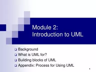
Module 2:Introduction to UML • Background • What is UML for? • Building blocks of UML • Appendix: Process for Using UML
UML History • OO languages appear mid 70’s to late 80’s (cf. Budd: communication and complexity) • Between ’89 and ’94, OO methods increased from 10 to 50. • Unification of ideas began in mid 90’s. • Rumbaugh joins Booch at Rational ’94 • v0.8 draft Unified Method ’95 • Jacobson joins Rational ’95 • UML v0.9 in June ’96 • UML 1.0 offered to OMG in January ’97 • UML 1.1 offered to OMG in July ’97 • Maintenance through OMG RTF • UML 1.2 in June ’98 • UML 1.3 in fall ’99 • UML 1.5 http://www.omg.org/technology/documents/formal/uml.htm • UML 2.0 underway http://www.uml.org/ • IBM-Rational now hasThree Amigos • Grady Booch - Fusion • James Rumbaugh – Object Modeling Technique (OMT) • Ivar Jacobson – Object-oriented Software Engineering: A Use Case Approach (Objectory) • ( And David Harel - StateChart) • Rational Rose http://www-306.ibm.com/software/rational/ pre-UML UML 1.x UML 2.0
Unified Modeling Language (UML) • An effort by IBM (Rational) – OMG to standardize OOA&D notation • Combine the best of the best from • Data Modeling (Entity Relationship Diagrams); Business Modeling (work flow); Object Modeling • Component Modeling (development and reuse - middleware, COTS/GOTS/OSS/…:) • Offers vocabulary and rules for communication • Not a process but a language de facto industry standard
UML is for Visual Modeling A picture is worth a thousand words! - standard graphical notations: Semi-formal - for modeling enterprise info. systems, distributed Web-based applications, real time embedded systems, … Sales Representative Places Order Customer Fulfill Order Item Business Process via Ships the Item - Specifying & Documenting: models that are precise, unambiguous, complete • UML symbols are based on well-defined syntax and semantics. • analysis, architecture/design, implementation, testing decisions. - Construction:mapping between a UML model and OOPL.
Three (3) basic building blocks of UML (cf. Harry) Water have Fresh water Rivers Oceans • Things -important modeling concepts • Relationships - tying individual things • Diagrams - grouping interrelated collections of things and relationships have have Salt water live in have Fish have Crocodiles Penguins Just glance thru for now
3 basic building blocks of UML - Things • UML 1.x • Structural— nouns/static of UML models (irrespective of time). • Behavioral— verbs/dynamic parts of UML models. • Grouping— organizational parts of UML models. • Annotational— explanatory parts of UML models. Main
Structural Things in UML- 7 Kinds (Classifiers) • Nouns. • Conceptual or physical elements. Interface Node Active Class (processes/threads) Component (collection of externally Visible ops) Class (replaceable part, realizes interfaces) (computational resource at run-time, processing power w. memory) Event Mgr thread time Start suspend( ) stop( ) Student std_id grade changeLevel( ) setGrade( ) getGrade( ) Course.cpp IGrade <<interface>> IGrade UnivWebServer setGrade() getGrade() Manage Course Registration Register for Courses Use Case Collaboration (chain of responsibility shared by a web of interacting objects, structural and behavioral) • (a system service • sequence of • Interactions w. actor)
Behavioral Things in UML • Verbs. • Dynamic parts of UML models: “behavior over time” • Usually connected to structural things. • Two primary kinds of behavioral things: • Interaction • a set of objects exchanging messages, to accomplish a specific purpose. ask-for-an-A harry: Student katie: Professor name = “Harry Kid” name = “Katie Holmes” • State Machine • specifies the sequence of states an object or an interaction goes through during its lifetime in response to events. received-an-A/ buy-beer inStudy inParty sober/turn-on-PC
Grouping Things in UML: Packages - For organizing elements (structural/behavioral) into groups. - Purely conceptual; only exists at development time. - Can be nested. - Variations of packages are: Frameworks, models, & subsystems. University Administration Course Manager Course Manager Student Admission -Student +Department Annotational Things in UML: Note - Explanatory/Comment parts of UML models - usually called adornments - Expressed in informal or formal text. flexible drop-out dates operation() {for all g in children g.operation() }
3 basic building blocks of UML - Relationships Student University attends 1. Associations Structural relationship that describes a set of links, a link being a connection between objects. variants: aggregation & composition Student Person 2. Generalization a specialized element (the child) is more specific the generalized element. Student 3. Realization one element guarantees to carry out what is expected by the other element. (e.g, interfaces and classes/components; use cases and collaborations) IGrade Student harry: Student <<instanceOf>> 4. Dependency a change to one thing (independent) may affect the semantics of the other thing (dependent). (direction, label are optional)
3 basic building blocks of UML- Diagrams A connected graph: Vertices are things; Arcs are relationships/behaviors. UML 1.x: 9 diagram types. UML 2.0: 12 diagram types Structural Diagrams Represent the static aspects of a system. • Class; Object • Component • Deployment Structural Diagrams • Class; Object • Component • Deployment • Composite Structure • Package Interaction Diagrams • Sequence; Communication • Interaction Overview • Timing Behavioral Diagrams • Use case • Statechart • Activity Behavioral Diagrams Represent the dynamic aspects. • Use case • Sequence; Collaboration • Statechart • Activity
Diagrams in UML The UTD wants to computerize its registration system • The Registrar sets up the curriculum for a semester • Students select 3 core courses and 2 electives • Once a student registers for a semester, the billing system is notified so the student may be billed for the semester • Students may use the system to add/drop courses for a period of time after registration • Professors use the system to set their preferred course offerings and receive their course offering rosters after students register • Users of the registration system are assigned passwords which are used at logon validation What’s most important?
Diagrams in UML – Actors in Use Case Diagram The UTD wants to computerize its registration system • The Registrar sets up the curriculum for a semester • Students select 3 core courses and 2 electives • Once a student registers for a semester, the billing system is notified so the student may be billed for the semester • Students may use the system to add/drop courses for a period of time after registration • Professors use the system to set their preferred course offerings and receive their course offering rosters after students register • Users of the registration system are assigned passwords which are used at logon validation • An actor is someone or some thing that must interact with the system under development Registrar Student Billing System Professor
Diagrams in UML – Use Cases in Use Case Diagram • A use case is a sequence of interactions between an actor and the system Maintain Curriculum The UTD wants to computerize its registration system • The Registrar sets up the curriculum for a semester • Students select 3 core courses and 2 electives • Once a student registers for a semester, the billing system is notified so the student may be billed for the semester • Students may use the system to add/drop courses for a period of time after registration • Professors use the system to set their preferred course offerings and receive their course offering rosters after students register • Users of the registration system are assigned passwords which are used at logon validation Register for Courses Registrar Student Billing System Request Course Roster Set Course Offerings Professor
Diagrams in UML – Use Case Diagram UTD Registration System system boundary • Use case diagrams depict the relationships between actors and use cases Maintain Curriculum Registrar Register for Courses Billing System Student Manage Seminar Request Course Roster Anything wrong? Set Course Offerings Professor
Diagrams in UML -Uses and Extends in Use Case Diagram A uses relationship shows behavior common to one or more use cases An extends relationship shows optional/exceptional behavior <<uses>> <<extends>> Register for courses <<uses>> Register for Distance Learning courses Logon validation <<uses>> Maintain curriculum Create course <<uses>> Maintain Schedule
Diagrams in UML –Flow of Events for each use case: Typical contents:How the use case starts and ends Normal flow of events (focus on the normal first!) Alternate/Exceptional flow of events • This use case begins after the Registrar logs onto the Registration System with a valid password. • The registrar fills in the course form with the appropriate semester and course related info. • The Registrar requests the system to process the course form. • The system creates a new course, and this use case ends Flow of Events for Creating a Course Registrar Create Course
Diagrams in UML – Interaction Diagrams A use case diagram presents an outside view of the system. Then, how about the inside view of the system? • Interactiondiagramsdescribe how use cases are realized in terms of interacting objects. • Two types of interaction diagrams • Sequence diagrams • Collaboration (Communication) diagrams
Diagrams in UML - Sequence Diagram • A sequence diagram displays object interactions arranged in a time sequence course form : theManager : CurriculumManager CourseForm : Registrar Create Course Registrar This use case begins after the Registrar logs onto the Registration System with a valid password. The registrar fills in the course form with the appropriate semester and course related info. The Registrar requests the system to process the course form. The system creates a new course, and this use case ends 1: set course info 2: request processing 3: add course aCourse : 4: <<create>> Course Traceability!
Diagrams in UML – Collaboration (Communication) • Displays object interactions organized around objects and their direct links to one another. • Emphasizes the structural organization of objects that send and receive messages. course form: 1: set course info CourseForm theManager : course form : 2: request processing CurriculumManager CourseForm : Registrar 1: set course info 2: request processing : Registrar 3: add course 3: add course aCourse: 4: <<create>> Course theManager : aCourse: CurriculumManager Course 4: <<create>> Traceability!
Diagrams in UML – Collaboration (Communication) • What would be the corresponding collaboration diagram? registration registration math 101 math 101 : Student form manager section 1 1: fill in info 2: submit 3: add course(Sue, math 01) 4: are you open? 5: are you open? 6: add (Sue) 7: add (Sue) Which use case could this be for? How about <----------
Sequence Diagrams & Some Programming :Purchase :Selection purchase buyMajor buyMinor create(cashTender) :Payment public Class Selection { private Purchase myPurchase = new Purchase(); private Payment myPayment; public void purchase() { myPurchase.buyMajor(); myPurchase.buyMinor(): myPayment = new Payment( cashTender ); //. . } // . . }
Interactions - Modeling Actions asynchronous in 2.0 (stick arrowhead) – no return value expected at end of callee activation activation of caller may end before callee’s half arrow in 1.x • Simple • Call • Return • Send c : Client 1 p : PlanningAgent : TicketAgent <<create>> actual parameter setItenerary( i ) calculateRoute() loop return return value route call on self for each conference <<destroy>> X end of object life notify() send destroy: e.g., in C++ manual garbage collection; in Java/C#, unnecessary natural death/ self destruction
Sequence Diagrams – Generic vs. Instance linking sequence diagrams • 2 forms of sd: • Instance sd: describes a specific scenario in detail; no conditions, branches or loops. • Generic sd: a use case description with alternative courses. concurrent lifelines • for conditionals • for concurrency ob3:C3 ob3:C3 ob3:C3 ob3:C3 op1 ob1:C1 [x>0] foo(x) ob2:C2 conditional [x<0] bar(x) do(z) do(w) [z=0] jar(z) [z=0] jar(z) recurse() Here, conditional or concurrency? recursion
Interaction Diagram: sequence vs communication objects object role:ClassName s2 : StockQuoteSubscriber p : StockQuotePublisher s1 : StockQuoteSubscriber classifiers or their instances, use cases or actors. attach(s1) attach(s2) Procedure call, RMI, JDBC, … Observer design pattern Time notify() update() {update < 1 minutes} Activations - Show duration of execution - Shows call stack - Return message Implicit at end of activation Explicit with a dashed arrow getState() update() getState() 3 : notify() 4 : update() s1 : StockQuoteSubscriber 1 : attach(s1) 6 : getState() p : StockQuotePublisher 5 : update() s2 : StockQuoteSubscriber 2 : attach(s2) 7 : getState()
Diagrams in UML - Class Diagrams • Recall: A class is a collection of objects with common structure, common behavior, common relationships and common semantics • Some classes are shown through the objects in sequence/collaboration diagram • A class diagram shows the existence of classes and their relationships theManager : CurriculumManager Course CurriculumManager aCourse : 4: <<create>> Course Traceability! RegistrationManager registration registration form manager 3: add course(Sue, math 01) addCourse(Student,Course)
Diagrams in UML - Class Diagrams: static structure in the system ScheduleAlgorithm RegistrationForm CurriculumManager RegistrationManager addStudent(student, course) Course name numberCredits Student open() addStudent(StudentInfo) major Professor CourseOffering tenureStatus location open() addStudent(StudentInfo) • Naming & (often) 3 Sections; • Inheritance (as before); • Relationships - Multiplicity and Navigation 1 0..* 0..* 1 1 0..* User name 1 1..10 1..* 4 1 0..4 Reading?
Diagrams in UML – Object Diagrams • Shows a set of objects and their relationships. • As a static snapshot. harry: Student ooad06S: Course name = “OOAD” name = “Harry Kid” katie: Professor ooado: CourseOffering name = “Katie Holmes” location = “Fujitsu” Anything wrong? arch06F: Course tom: Student name = “Sw Architecture” harry1: Professor name = “Tom Cruise” name = “Harry William” alg06F: Course surie: Professor arch: CourseOffering name = “Adv Algorithms” name = “Surie Holmes” location = “UTD”
Diagrams in UML – State Transition Diagram(Statechart Diagram) Add student [count < 10] Add Student / Set count = 0 Initialization Open do: Initialize course Cancel Cancel [ count = 10 ] Canceled do: Notify registered students Closed Cancel do: Finalize course • The life history (often of a given class: from class to object behavior) • States, transitions, events that cause a transition from one state to another • Actions that result from a state change initial (internal) condition event/action state State name entry: Register student activity exit: Increment count final What life history/class is this for? Anything wrong? …until the drop date?
Diagrams in UML– Activity Diagrams • A special kind of statechart diagram that shows the flow from activity to activity. initial Initialize course activity Add student fork/spawn Notify Registrar Notify Billing What is this for? Traceability??? Synchronization [else] Can you model this using SD? Can you model this using CD? [ count < 10 ] guard Close course final
Diagrams in UML – Component Diagram Student Professor Student Course Professor Course Offering shows the organizations and dependencies among a set of components (mostly <<uses>>). In UML 1.1, a component represented implementation items, such as files and executables; … In UML 2.0, a component is a replaceable/reusable, architecture/design-time constructw. interfaces Register.exe Billing.exe Billing User People.dll Course Course.dll
Diagrams in UML – Deployment Diagram Registrar Webserver Course Oracle Server • shows the configuration of run-time processing elements and the software processes living on them. • visualizes the distribution of components across the enterprise. Register.exe Course CourseOffering RMI, sockets TCP/IP wireless Library Server Main Building Solaris People.dll Billing.exe Dorm PC People Database Student Professor
3 basic building blocks of UML- Diagrams Using UML Concepts in a Nutshell • Here, UML 1.x first • (UML 2.0 later) • Use case • Sequence; • Collaboration • (Communication) • Class; • Object • Statechart • Activity • Component • Deployment • Display the boundary of a system & its major functions using use cases and actors • Illustrate use case realizations with interaction diagrams • Represent a static structure of a system using class diagrams • Model the behavior of objects with state transition diagrams • Reveal the physical implementation architecture with component & deployment diagrams • Extend your functionality with stereotypes
Summary • Background • What is UML for (both 1.x and 2.0)? for visualizing, specifying, constructing, and documenting models • Building blocks of UML Things, Relationships (4 kinds) and Diagrams (9 different kinds)
Extensibility of UML • Stereotypes (<< >>) can be used to extend the UML notational elements • Stereotypes may be used to classify and extend associations, inheritance relationships, classes, and components • Examples: • Class stereotypes: boundary, control, entity, utility, exception • Inheritance stereotypes: uses and extends • Component stereotypes: subsystem • Stereotypes — extends vocabulary (metaclass in UML metamodel) • Tagged values — extends properties of UML building blocks (i.e., metamodel) • Constraints — extend the semantics of UML building blocks. More on this later
Architecture & Views (You can skip this part on the first reading) UML is for visualizing, specifying, constructing, and documenting with emphasis on system architectures (things in the system and relationships among the things) from five different views Architecture - set of significant decisions regarding: • Organization of a software system. • Selection of structural elements & interfaces from which a system is composed. • Behavior or collaboration of elements. • Composition of structural and behavioral elements. • Architectural style guiding the system. Design View Implementation View vocabulary functionality system assembly configuration mgmt. Use Case View behavior Process View Deployment View system topology distribution delivery installation performance scalability throughput
Views Use Case View • Use Case Analysis is a technique to capture business process from user’s perspective. • Encompasses the behavior as seen by users, analysts and testers. • Specifies forces that shape the architecture. • Static aspects in use case diagrams; Dynamic aspects in interaction (statechart and activity) diagrams. Design View • Encompasses classes, interfaces, and collaborations that define the vocabulary of a system. • Supports functional requirements of the system. • Static aspects in class and object diagrams; Dynamic aspects in interaction diagrams. Process View • Encompasses the threads and processes defining concurrency and synchronization. • Addresses performance, scalability, and throughput. • Static and dynamic aspects captured as in design view; emphasis on active classes. Implementation View • Encompasses components and files used to assemble and release a physical system. • Addresses configuration management. • Static aspects in component diagrams; Dynamic aspects in interaction diagrams. Deployment View • Encompasses the nodes that form the system hardware topology. • Addresses distribution, delivery, and installation. • Static aspects in deployment diagrams; Dynamic aspects in interaction diagrams.
Rules of UML • Well formed models— semantically self-consistent and in harmony with all its related models. • Semantic rules for: • Names— what you can call things. • Scope— context that gives meaning to a name. • Visibility— how names can be seen and used. • Integrity — how things properly and consistently relate to one another. • Execution— what it means to run or simulate a dynamic model. • Avoid models that are Elided— certain elements are hidden for simplicity. Incomplete— certain elements may be missing. Inconsistent— no guarantee of integrity.
Process for Using UML How do we use UML as a notation to construct a good model? • Use case driven— use cases are primary artifact for defining behavior of the system. • Architecture-centric— the system’s architecture is primary artifact for conceptualizing, constructing, managing, and evolving the system. • Iterative and incremental— managing streams of executable releases with increasing parts of the architecture included. The Rational Unified Process (RUP)
Process for Using UML -Iterative Life Cycle • It is planned, managed and predictable …almost • It accommodates changes to requirements with less disruption • It is based on evolving executable prototypes, not documentation • It involves the user/customer throughout the process • It is risk driven Primary phases • Inception— seed idea is brought up to point of being a viable project. • Elaboration— product vision and architecture are defined. (http://www.utdallas.edu/~chung/OOAD_SUMMER04/HACS_vision_12.doc) • Construction— brought from architectural baseline to point of deployment into user community. • Transition— turned over to the user community.
Process for Using UML -Iterative Approach • Three Important Features • Continuous integration - Not done in one lump near the delivery date • Frequent, executable releases - Some internal; some delivered • Attack risks through demonstrable progress - Progress measured in products, not documentation or engineering estimates • Resulting Benefits • Releases are a forcing function that drives the development team to closure at regular intervals - Cannot have the “90% done with 90% remaining” phenomenon • Can incorporate problems/issues/changes into future iterations rather than disrupting ongoing production • The project’s supporting elements (testers, writers, toolsmiths, QA, etc.) can better schedule their work
Process for Using UML - Risk Reduction Drives Iterations Define scenarios to address highest risks • Plan Iteration N • Cost • Schedule Initial Project Risks Initial Project Scope • Develop Iteration N • Collect cost and quality metrics Iteration N Assess Iteration N • Revise Overall • Project Plan • Cost • Schedule • Scope/Content Risks Eliminated • Revise Project Risks • Reprioritize
Process for Using UML - Use Cases Drive the Iteration Process Inception Elaboration Construction Transition Iteration 1 Iteration 2 Iteration 3 Each iteration is defined in terms of the scenarios it implements “Mini-Waterfall” Process • Results of previous iterations • Up-to-date risk assessment • Controlled libraries of models, code, and tests Selected scenarios Iteration Planning Reqs Capture Analysis & Design Implementation Test Release description Updated risk assessment Controlled libraries Prepare Release
Points to Ponder Are Sequence and Collaboration Diagrams Isomorphic?
Points to Ponder • How much unification does UML do? Consider the Object Model Notation on the inside cover on the front and back of the textbook "Object Oriented Modeling and Design" by Rumbaugh, et.al. • List the OMT items that do not exist in UML • List the UML items that do not exist in OMT • For those items of OMT for which UML equivalents exist, map the notation to UML. • Where would you want to use stereotypes? • Model the “Business Process” on page 6 in UML. • Map the four (4) phases of the RUP to the traditional software lifecycle. • If an object refers to a concept, can an object refer to a concept of an concept? Consider some examples. • What would be the essential differences between a property and an attribute? Consider some examples. • What is the syntax and semantics of a class diagram? • In Component-Based Software Engineering (CBSE), components are the units, or building blocks, of a (distributed) software system. What kind of building blocks of UML can be components for CBSE?