Download
1 / 35
460 likes | 1.37k Vues
Nuclear Magnetic Resonance (NMR) Spectroscopy. Dr. Vincent J. Storhaug. The Fourier Transform Pulsed NMR Technique. time. Delay. Pulse. Delay. Acquisition. time. z. z. y. y. x. x. The Fourier Transform Pulsed NMR Technique (Rotating Frame of Reference). time. 90º. M 0. RF. M 0.

E N D
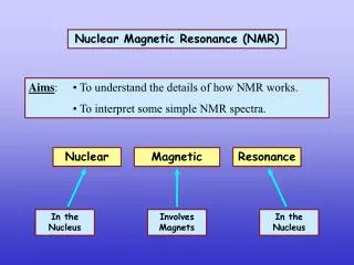
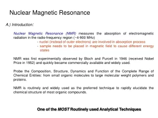
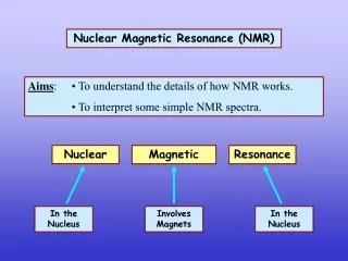
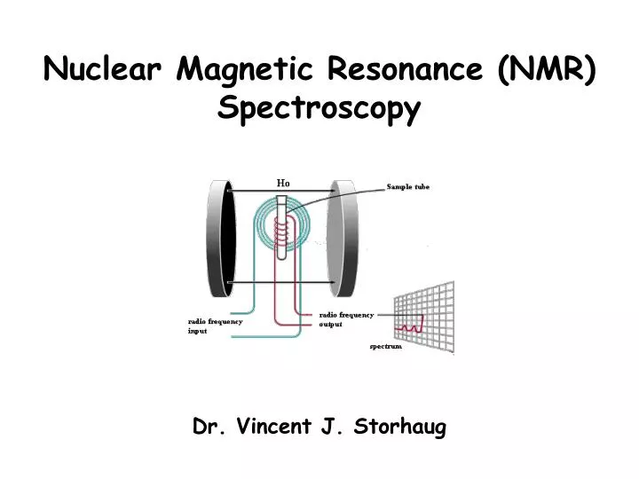
Nuclear Magnetic Resonance (NMR) Spectroscopy Dr. Vincent J. Storhaug
The Fourier Transform Pulsed NMR Technique time Delay Pulse Delay Acquisition time
z z y y x x The Fourier Transform Pulsed NMR Technique(Rotating Frame of Reference) time 90º M0 RF M0 B1 B0 B0
Basics of Fourier Transform NMR: Measuring the Precession Frequency
Relaxation Process in NMR Spin-Lattice Relaxation, T1 The absorbed energy is lost through vibrational and rotational motion to the magnetic components of the “lattice” of the sample. Problem: The temperature of the sample can rise over time. Spin-Lattice relaxation processes cause an exponential decay of the excited state population. The more viscous a sample is, or the more restricted the motion of a molecule is, the larger the T1. Spin-Lattice relaxation is the slower of the relaxation processes. Spin-Spin Relaxation, T2 Several processes are “lumped” under this term, but one of the predominant techniques is spin diffusion, a process requiring neighboring nuclei to have the same precession rates, but different magnetic quantum numbers. Another cause is a disruption in the homogeneity of the magnetic field through the sample caused by the sample itself. (e.g. – formation of dimers, trimers, etc. that change the relaxation rates of nuclei.) Spin-Lattice relaxation is the faster of the relaxation processes. Thus, T2 is the primary influence on line broadening in the spectrum.
z z z z y y y y x x x x Spin-Spin Relaxation, T2 Mxy time z y x time
z z z z z z z z y y y y y y y y x x x x x x x x Longitudinal Spin-Lattice Relaxation, T1 Mxy time Mz My
Longitudinal Spin-Lattice Relaxation, T1 The time constant, T1,describes how MZ returns to its equilibrium value. The equation governing this behavior as a function of the time t after its displacement is: T1 is therefore defined as the time required to change the Z component of magnetization by a factor of e. If the net magnetization is placed along the “-Z” axis (i.e. – pw = 180º), it will gradually return to its equilibrium position along the “+Z” axis at a rate governed by T1. The equation governing this behavior as a function of the time t after its displacement is:
Signal Intensity Time Basics of Fourier Transform NMR: The Free Induction Decay +
Signal Intensity Time Basics of Fourier Transform NMR: The Free Induction Decay + Signal Intensity Frequency
Signal to Noise Improvement With “digital” summations of FIDs (or rather, transients), where n is the total number of scans acquired.
Signal to Noise Improvement: Practical Considerations • Running a 13C NMR spectrum. • Not limited so much in the amount of sample, but by the solubility of the compound in the available solvent (deuterated CDCl3) • Ran the sample for 4 hours, and it looks like: In order to increase the S/N by a factor of 2, this would need to run for 16 hours. In order to increase the S/N by a factor of 4, this would need to run for 64 hours (almost 3 days).
Hardware of NMR: The Superconducting Magnet Standard design for 300-600* MHz magnet systems
Hardware of NMR: General Overview of Components S N RF Amplifier Time Swept Computer and Fourier Transform RF Transmitter Phase Sensitive Detector Pulse Switch Frequency Synthesizer Output (Video/Hard Copy)
Hardware of NMR: General Overview of Components S N “Preamp” Directional Coupler RF Amplifier Phase Sensitive Detector HIGH SPEED Data Recorder RF Transmitter Computer to Perform FT Pulse Switch Frequency Synthesizer Output (Video/Hard Copy)
Hardware of NMR: Mercury Plus VT Control Communication Boards Frequency Synthesizers RF Transmitters RF Amplifiers Probe Magnet Leg/Interface PreAmplifiers Power Supply
Hardware of NMR: Unity Inova Communication Boards Low Band Freq. Synth. High Band Freq. Synth. RF Trans./Amp. For CH’s 1 & 2 RF Trans./Amp. For CH 3 VT Control Probe Magnet Leg/Interface PreAmplifiers Power Supply
Spectrometer Tuning Insert Inductor Stick Lock 1 4 1H-19F X Channel Proton X Channel Proton X Channel
Spectrometer Tuning Much like with the tuner on your TV or radio, you can tune the NMR probe to look for a certain frequency (range of frequencies). C1 Match L C2 Tune Rtotal 0 100
Spectrometer Tuning When we discuss the quality of tuning, we refer to the “Q value”: The higher the Q value the higher the sensitivity. Engineers like to use smaller R and larger L, but… because of the tuning equation, and the fact that variable capacitors normally only come in 1 – 30 pF) …
Spectrometer Tuning/Matching “Impedance mismatch” can lead to a significant attenuation of the NMR signal. 75 Ω 50 Ω 0 100
Spectrometer Tuning/Matching “Impedance mismatch” can lead to a significant attenuation of the NMR signal. C1 Match L C2 Tune Rtotal 0 100
Spectrometer Tuning/Matching C1 is used to match the impedance of the circuit. Maximum power transfer is achieved when the load impedance matches the source impedance. The “source impedance” is that which comes from the high power amplifier. (coaxial, 50Ω). 0 100 0 100
Spectrometer Tuning and the Gated Frequency Generator 0 100 E = hv hΔv Δt ~ h Δv = spectral width (Hz) Δt = pulse width (s) Long (90º Pulse) Short (30º Pulse) 100 0
Spectrometer Tuning Lock 1 4 1H-19F X Channel Proton X Channel Proton X Channel
Spectrometer Drift: Locking Time Resonance Frequency • We DO want to use one of the frequencies as a “feedback loop” to correct for any drift in the field with time. • We DO NOT want to use one of the frequencies that we wish to “observe” – Heisenberg Uncertainty Principle.
Using the Spectrometer Lock for Shimming • What is Shimming? In order for signals to be symmetrical and “sharp”, the magnetic field must pass through the sample homogeneously; however, there are problems: • NMR Tube never filled to EXACTLY the same level. • Different deuterated solvents do not have the same physical properties, e.g. – VISCOSITY • NMR tube may never be inserted at EXACTLY the same orientation in the sample holder, i.e. - spinner. • Microscopic particulates/colloidal particles. • Tube quality may not be the same: • Wilmad • Norell • Kontes • Aldrich (Fisher) • Chemglass • How do we correct for these problems?
Using the Spectrometer Lock for Shimming Shim Stack
Purpose of the Phase Cycle • Unwanted COHERENT signals can be received from a variety • of sources: • Imbalance of spectrometer hardware • Coherent noise (rf “pickup”) • Artifacts generated by multipulse techniques (2D) • Other sources • The way to distinguish noise from signal is to phase cycle the pulse and the • “phase sensitive” detector. • Actual phase cycle depends on the nmr technique • Typically for a 1D experiment, you have a phase cycle of 4 or 8 • Should always make the number of scans a multiple of the phase cycle x Receiver Phase Pulse Phase O (+x) O (+x) y 9O (+y) 9O (+y) 180 (-x) 180 (-x) 270 (-y) 270 (-y)
Purpose of the Phase Cycle O (+x) 180 (-x)
Space Requirements Needed to House an 800 MHz Unshielded Magnet