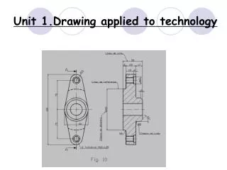
Unit 2.Drawing applied to technology
Unit 2.Drawing applied to technology. Unit 2.Drawing applied to technology. What are we going to see in this unit? 2.1 Drawing tools and how to use them 2.2 Drafts and sketches 2.3 Drafting scale 2.4 Diedric system 2.5 Marking and standardizing. 2.1 Drawing materials and instruments.

Unit 2.Drawing applied to technology
E N D
Presentation Transcript
Unit 2.Drawing applied to technology • What are we going to see in this unit? • 2.1 Drawing tools and how to use them • 2.2 Drafts and sketches • 2.3 Drafting scale • 2.4 Diedric system • 2.5 Marking and standardizing
2.1 Drawing materials and instruments Paper • Paper is made of cellulose that is obtained from trees • The paper size that we use is A4 . It is the result of dividing 1 m2 (A0) four times by half the longest side.
2.1 Drawing materials and instruments Pencil • A pencil is lead in a wooden casing. The lead is made with graphite and clay Lead clay Woodencasing Graphite
2.1 Drawing materials and instruments Pencil hardness The more clay it contains the harder the lead will be. We use letter H for hard pencils and letter B for soft ones. Hard: H Soft: B less clay More clay Technical drawing Artistic drawing
2.1 Drawing materials and instruments Mechanicalpencils Theyholdgraphite lead. They can beusedfortechnicaldrawingifusedwitha soft lead. ERASERS Erasers are made of rubber; theyabsorb graphite and erase it.
2.2 DRAFT AND SKETCH • DRAFT: Itis a free hand drawing (with just a pencil). We show an idea or object without totally defining it.
2.2 DRAFT AND SKETCH • ATTENTION! • A DRAFT IS NOT A BAD DRAWING AND A SKETCH IS NOT A GOOD DRAWING !!!!!!
2.2 DRAFT AND SKETCH The sketch: Itis a free handdrawingtoo, butitincludesthemeasurements, thereforeit shows the precise size and a shape similar tothe final drawing. measure Page 41
2.2 DRAFT AND SKETCH • Activity: draw a sketch of your home cupboard.
2.2 DRAFT AND SKETCH the Sketch
2.3 Drafting scale • We define scale as the relationship between the size of the drawing and the real object. A model uses a reduction scale
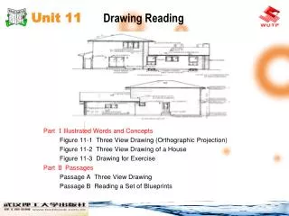
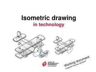
2.4 Diedric system The diedric system represents the objects using a perpendicular projection on a plane
2.4 Diedric system The projection or VIEW consists of drawing just what we see when we are perpendicular to the object and to the plane Page 28
Top view Profile view Front view Profile view Front view Top view 2.4 Diedric system To define an object we only need 3 views, top, front and profile: • Top view: from the top of the object • Front view: facing the object • Profile view: from the side
Right profile front front Left profile top top 2.4 Diedric system Diedric Rules • The front is usually indicated with an arrow • The views distribution • The front is always on top of the top view • The profile is situated the other way round, that is, the left profile is situated on the right
2.4 Diedric system Remember: • The same height: the object has the same height on the floor and on the profile views • The same width: on the front and on the top views • The same depth: on the floor and on the profile views
2.4 Diedric system • Exercise: Draw the front, left profile and floor views of the class chair
2.4 Diedric system • Exercise: Draw the front, profile and floor views of the class chair
2.4 Diedric system Where do we have to be situated to see these objects like circles?
2.4 Diedric systemExercise 11: Complete the views of the following objects Page 31
2.4 Diedric systemExercise 11: Complete the views of the following objects
2.4 Diedric systemExercise 11: Complete the views of the following objects
2.4 Diedric systemExercise 11: Complete the views of the following objects
2.4 Diedric system • Non visible lines: when we know there is a hidden line we have to draw it using a discontinuous line hidden line
2.5 Marking and standardizing • Standardizing is the group of rules that defines technical drawing. • For example: • For paper size we use the DIN rule: A0,A1,A2… • The lines are: • Thick continuous lines: are used to outline objects • Thick discontinuous lines: indicate hidden lines • Thin continuous lines: are used for auxiliary measures and reference lines
Reference line 2.5 Marking and standardizing Measure Dimensionline ExtensionLine
2.5 Marking and standardizing Outsidethickcontinuous line a discontinuousline of mediumthicknessfor a hiddenedge
2.5 Marking and standardizing Marking : indicating the real dimensions of the object
Vocabulary • Paper size • Cellulose • Clay, graphite, lead • Hard and soft pencils • Erasers, technical pencil • Sixty and forty-five degree rules • Sketch, draft, free hand drawing, measures • Scale, real and drawn size, reduction, enlargement scales • To be reduced 100 times… • Length, height, width • Long, high, wide.