The Cellular Concept
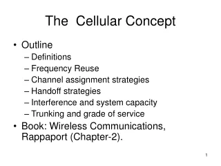
The Cellular Concept. Outline Definitions Frequency Reuse Channel assignment strategies Handoff strategies Interference and system capacity Trunking and grade of service Book: Wireless Communications, Rappaport (Chapter-2). Simplex, half duplex, full duplex.


The Cellular Concept
E N D
Presentation Transcript
The Cellular Concept • Outline • Definitions • Frequency Reuse • Channel assignment strategies • Handoff strategies • Interference and system capacity • Trunking and grade of service • Book: Wireless Communications, Rappaport (Chapter-2).
Basic cellular system consists of • Mobile stations (e.g. mobile phones) (MS) • users transceiver terminal (handset, mobile) • Base stations (BS) • fixed transmitter usually at centre of cell • includes an antenna, a controller, and a number of receivers • Mobile switching center (MSC) • Sometimes called a mobile telephone switching office (MTSO) • handles routing of calls in a service area • tracks user • connects to base stations and PSTN
1G Mobile Phone Dr. Martin Cooper of Motorola, made the first US analogue mobile phone call on a larger prototype model in 1973. This is a reenactment (tekrarlamak) in 2007
Mobile switching center (MSC) • Coordinates the activities of all the base stations • Connect the entire cellular system to the PSTN • Accommodates all billing and system maintenance functions
A group of local base stations are connected (may be wire) to a mobile switching center (MSC). MSC is connected to the rest of the world (normal telephone system) or to other MSCs (by wires). MSC Public (Wired) Telephone Network MSC MSC MSC
Cluster • Each MSC coordinates a number of base stations • The set of base stations controller by a single MSC is called a CLUSTER • The number of base stations in a cluster is usually denoted by the letter N
In AMPS the number of cells inside a cluster is 7 • On the other hand in GSM there are 3 or 4 cells inside a cluster
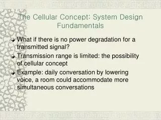
Old communication systems use a single high power transmitter and the coverage area is very large. The next base station was so far away that the interference was not an issue. • However, old systems support just a few users
Cellular Networks OLD radio systems NEW (Cellular systems)
Hexagonal cell shape has been universally adopted, since it permits easy and manageable analysis of a cellular system. • The actual radio coverage of a cell is determined from field measurements or propagation prediction models.
For a given distance between the center of a polygon and its farthest perimeter points, the hexagon has the largest area among the sensible geometric cell shapes. • Thus, by using the hexagon geometry, the fewest number of cells can cover a geographic region, and the hexagon also closely approximates a circular radiation pattern which would occur for an omni-directional base station antenna and free space propagation.
When using hexagons to model coverage areas, base station transmitters are depicted as either being • In the center of the cell, or • On three of the six cell vertices. • Normally • Omni-directional antennas are used in center-excited cells • Sectored directional antennas are used in corner-excited cells. • Practical considerations usually do not allow base stations to be placed exactly as they appear in the hexagonal layout. Most system design permit a base station to be positioned up to one-fourth the cell radius from the ideal location.
Directional Antenna at Base Station With 120 degree antenna, we draw the cells as:
Coverage map example • Unfortunately cell coverage is normally neither hexagonal or circular • Figure shows coverage example from a city centre • Complicates radio planning
Radio planning tools • Radio planning is most often performed assisted by an automated process using a computer • Underlying functionality • Digital maps • Propagation modelling • System parameters and system performance • Traffic assumptions and theory • Often theoretical computer based modelling can be tuned by real life data • Propagation measurements • Live network traffic data
Cell Planning • k = the number of channels allocated to each cell in a cluster • N= cluster size (number of cells in a cluster) • M= number of clusters within a communication system • The number of channels available in a cluster is S=kN • The capacity of the cellular systems is C=MS which is C=MkN • The frequency reuse factor is 1/N
In order to tessellate (mozaikle dosemek) - to connect without gaps between adjacent cells – the geometry of the hexagons is such that the number of cells per cluster, N, can only have values N=i2+ij+j2 where i and j are non-negative integers, i.e., i>=0, j>=0 • The factor N is typically equal to 4, 7, 12, …..
Co-channel cells • Frequency reuse implies that in a given coverage area there are several cells that use the same set of frequencies. These cells are called c-channel cells, and the interference between signals from these cells is called co-channel interference.
HW (to be collected) Find the proof of: the number of cells in a cluster equals N=i2+ij+j2 Write a HW report including the proof. Please use your handwriting, computer typing is not accepted. Due: 4 Friday, November, 2011, 5.00 p.m