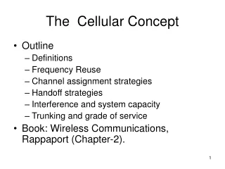
Chapter 2 The Cellular Concept
Chapter 2 The Cellular Concept. 2.1 Introduction to Cellular Systems. Solves the problem of spectral congestion and user capacity. Offer very high capacity in a limited spectrum without major technological changes. Reuse of radio channel in different cells.

Chapter 2 The Cellular Concept
E N D
Presentation Transcript
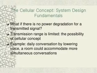
2.1 Introduction to Cellular Systems • Solves the problem of spectral congestion and user capacity. • Offer very high capacity in a limited spectrum without major technological changes. • Reuse of radio channel in different cells. • Enable a fix number of channels to serve an arbitrarily large number of users by reusing the channel throughout the coverage region.
2.2 Frequency Reuse • Each cellular base station is allocated a group of radio channels within a small geographic area called a cell. • Neighboring cells are assigned different channel groups. • By limiting the coverage area to within the boundary of the cell, the channel groups may be reused to cover different cells. • Keep interference levels within tolerable limits. • Frequency reuse or frequency planning • seven groups of channel from A to G • footprint of a cell - actual radio coverage • omni-directional antenna v.s. directional antenna
Consider a cellular system which has a total of S duplex channels. • Each cell is allocated a group of k channels, . • The S channels are divided among N cells. • The total number of available radio channels • The N cells which use the complete set of channels is called cluster. • The cluster can be repeated M times within the system. The total number of channels, C, is used as a measure of capacity • The capacity is directly proportional to the number of replication M. • The cluster size, N, is typically equal to 4, 7, or 12. • Small N is desirable to maximize capacity. • The frequency reuse factor is given by
Hexagonal geometry has • exactly six equidistance neighbors • the lines joining the centers of any cell and each of its neighbors are separated by multiples of 60 degrees. • Only certain cluster sizes and cell layout are possible. • The number of cells per cluster, N, can only have values which satisfy • Co-channel neighbors of a particular cell, ex, i=3 and j=2.
2.3 Channel Assignment Strategies • Frequency reuse scheme • increases capacity • minimize interference • Channel assignment strategy • fixed channel assignment • dynamic channel assignment • Fixed channel assignment • each cell is allocated a predetermined set of voice channel • any new call attempt can only be served by the unused channels • the call will be blocked if all channels in that cell are occupied • Dynamic channel assignment • channels are not allocated to cells permanently. • allocate channels based on request. • reduce the likelihood of blocking, increase capacity.
2.4 Handoff Strategies • When a mobile moves into a different cell while a conversation is in progress, the MSC automatically transfers the call to a new channel belonging to the new base station. • Handoff operation • identifying a new base station • re-allocating the voice and control channels with the new base station. • Handoff Threshold • Minimum usable signal for acceptable voice quality (-90dBm to -100dBm) • Handoff margin cannot be too large or too small. • If is too large, unnecessary handoffs burden the MSC • If is too small, there may be insufficient time to complete handoff before a call is lost.
Handoff must ensure that the drop in the measured signal is not due to momentary fading and that the mobile is actually moving away from the serving base station. • Running average measurement of signal strength should be optimized so that unnecessary handoffs are avoided. • Depends on the speed at which the vehicle is moving. • Steep short term average -> the hand off should be made quickly • The speed can be estimated from the statistics of the received short-term fading signal at the base station • Dwell time: the time over which a call may be maintained within a cell without handoff. • Dwell time depends on • propagation • interference • distance • speed
Handoff measurement • In first generation analog cellular systems, signal strength measurements are made by the base station and supervised by the MSC. • In second generation systems (TDMA), handoff decisions are mobile assisted, called mobile assisted handoff (MAHO) • Intersystem handoff: If a mobile moves from one cellular system to a different cellular system controlled by a different MSC. • Handoff requests is much important than handling a new call.
Practical Handoff Consideration • Different type of users • High speed users need frequent handoff during a call. • Low speed users may never need a handoff during a call. • Microcells to provide capacity, the MSC can become burdened if high speed users are constantly being passed between very small cells. • Minimize handoff intervention • handle the simultaneous traffic of high speed and low speed users. • Large and small cells can be located at a single location (umbrella cell) • different antenna height • different power level • Cell dragging problem: pedestrian users provide a very strong signal to the base station • The user may travel deep within a neighboring cell
Handoff for first generation analog cellular systems • 10 secs handoff time • is in the order of 6 dB to 12 dB • Handoff for second generation cellular systems, e.g., GSM • 1 to 2 seconds handoff time • mobile assists handoff • is in the order of 0 dB to 6 dB • Handoff decisions based on signal strength, co-channel interference, and adjacent channel interference. • IS-95 CDMA spread spectrum cellular system • Mobiles share the channel in every cell. • No physical change of channel during handoff • MSC decides the base station with the best receiving signal as the service station
2.5 Interference and System Capacity • Sources of interference • another mobile in the same cell • a call in progress in the neighboring cell • other base stations operating in the same frequency band • noncellular system leaks energy into the cellular frequency band • Two major cellular interference • co-channel interference • adjacent channel interference
2.5.1 Co-channel Interference and System Capacity • Frequency reuse - there are several cells that use the same set of frequencies • co-channel cells • co-channel interference • To reduce co-channel interference, co-channel cell must be separated by a minimum distance. • When the size of the cell is approximately the same • co-channel interference is independent of the transmitted power • co-channel interference is a function of • R: Radius of the cell • D: distance to the center of the nearest co-channel cell • Increasing the ratio Q=D/R, the interference is reduced. • Q is called the co-channel reuse ratio
For a hexagonal geometry • A small value of Q provides large capacity • A large value of Q improves the transmission quality - smaller level of co-channel interference • A tradeoff must be made between these two objectives
Let be the number of co-channel interfering cells. The signal-to-interference ratio (SIR) for a mobile receiver can be expressed as S: the desired signal power : interference power caused by the ith interfering co-channel cell base station • The average received power at a distance d from the transmitting antenna is approximated by or n is the path loss exponent which ranges between 2 and 4. close-in reference point
When the transmission power of each base station is equal, SIR for a mobile can be approximated as • Consider only the first layer of interfering cells • Example: AMPS requires that SIR be greater than 18dB • N should be at least 6.49 for n=4. • Minimum cluster size is 7
For hexagonal geometry with 7-cell cluster, with the mobile unit being at the cell boundary, the signal-to-interference ratio for the worst case can be approximated as
2.5.2 Adjacent Channel Interference • Adjacent channel interference: interference from adjacent in frequency to the desired signal. • Imperfect receiver filters allow nearby frequencies to leak into the passband • Performance degrade seriously due to near-far effect.
Adjacent channel interference can be minimized through careful filtering and channel assignment. • Keep the frequency separation between each channel in a given cell as large as possible • A channel separation greater than six is needed to bring the adjacent channel interference to an acceptable level.
2.5.3 Power Control for Reducing Interference • Ensure each mobile transmits the smallest power necessary to maintain a good quality link on the reverse channel • long battery life • increase SIR • solve the near-far problem
2.6 Trunking and Grade of Service • Erlangs: One Erlangs represents the amount of traffic density carried by a channel that is completely occupied. • Ex: A radio channel that is occupied for 30 minutes during an hour carries 0.5 Erlangs of traffic. • Grade of Service (GOS): The likelihood that a call is blocked. • Each user generates a traffic intensity of Erlangs given by H: average duration of a call. : average number of call requests per unit time • For a system containing U users and an unspecified number of channels, the total offered traffic intensity A, is given by • For C channel trunking system, the traffic intensity, is given as
2.7 Improving Capacity in Cellular Systems • Methods for improving capacity in cellular systems • Cell Splitting: subdividing a congested cell into smaller cells. • Sectoring: directional antennas to control the interference and frequency reuse. • Coverage zone : Distributing the coverage of a cell and extends the cell boundary to hard-to-reach place.
2.7.1 Cell Splitting • Split congested cell into smaller cells. • Preserve frequency reuse plan. • Reduce transmission power. Reduce R to R/2 microcell
Transmission power reduction from to • Examining the receiving power at the new and old cell boundary • If we take n = 4 and set the received power equal to each other • The transmit power must be reduced by 12 dB in order to fill in the original coverage area. • Problem: if only part of the cells are splited • Different cell sizes will exist simultaneously • Handoff issues - high speed and low speed traffic can be simultaneously accommodated
2.7.2 Sectoring • Decrease the co-channel interference and keep the cell radius R unchanged • Replacing single omni-directional antenna by several directional antennas • Radiating within a specified sector
Interference Reduction position of the mobile interference cells
2.7.3 Microcell Zone Concept • Antennas are placed at the outer edges of the cell • Any channel may be assigned to any zone by the base station • Mobile is served by the zone with the strongest signal. • Handoff within a cell • No channel re-assignment • Switch the channel to a different zone site • Reduce interference • Low power transmitters are employed