Download
1 / 102
1.02k likes | 1.84k Vues
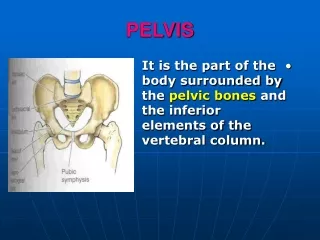
15.2 Pelvis A-P. Measure: A-P at Trochanters Protection: Males:Bell Females: None SID: 40” Table Bucky No Tube Angle Film: 17” x 14” I.D. up. Pelvis A-P. The Vertical CR is used to center the table and lock wheel locks. Males: place belt for bell at level of ASIS.

E N D
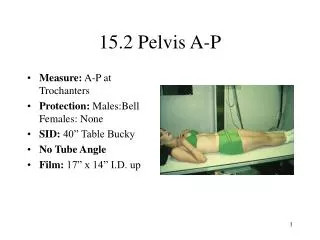
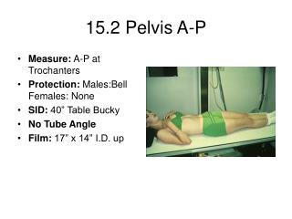
15.2 Pelvis A-P • Measure: A-P at Trochanters • Protection: Males:Bell Females: None • SID: 40” Table Bucky • No Tube Angle • Film: 17” x 14” I.D. up
Pelvis A-P • The Vertical CR is used to center the table and lock wheel locks. • Males: place belt for bell at level of ASIS. • Patient lies supine on the table. • Heels and Toes are together or heels may be apart with toes together.
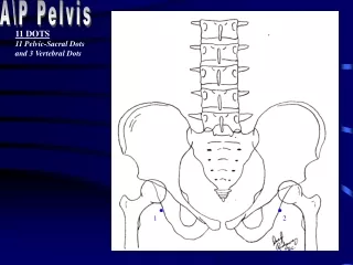
Pelvis A-P • Horizontal CR: 1” to 1.5” superior to Symphysis pubis • Vertical CR: mid-sagittal • Film centered to horizontal CR. • Collimation: slightly less than film size. • Breathing Instructions: Full expiration
Pelvis A-P Film • The pelvis should be centered on film. • Rotation should be avoided. • Both femurs will be in true A-P position if feet were properly positioned.
15.3 Pelvis Bilateral Frog leg Lateral • Measure: A-P at Trochanters • Protection: Males:Bell Females: None • SID: 40” Table Bucky • No Tube Angle • Film: 17” x 14” I.D. up
Pelvis Frog Leg Lateral • The Vertical CR is used to center the table and lock wheel locks. • Males: place belt for bell at level of ASIS. • Patient lies supine on the table. • Patient places heels together with knees bent.
Pelvis Frog Leg Lateral • The patient then externally rotates legs as far as possible. • A sponge may be used under the affected side to improve comfort. • Watch the placement of the bell on male patients as it is prone to be too high on this view.
Pelvis Frog Leg Lateral • Horizontal CR: 1 1/2” superior to symphysis pubis • Vertical CR: mid-sagittal • Film centered to horizontal CR. • Collimation: slightly less than film size. • Breathing Instructions: Full expiration
Pelvis Frog Leg Lateral Film • The pelvis should be centered on film. • Rotation should be avoided. Note rotation on this film. • Both femurs will be in a lateral oblique position. • Note that bell is too high and blocks view of symphysis.
15.4 Hip Unilateral A-P • Measure: A-P at trochanters • Protection: Bell: males: Females: None • SID: 40” Bucky or Table Bucky • No tube angle • Film: 10” x 12 I.D. up
Hip Unilateral A-P • This view may be taken erect or supine. • For supine view, center and lock table to vertical CR. • Place belt for bell on patient at level of the ASIS. • Patient stands or lies facing the tube.
Hip Unilateral A-P • The leg is internally rotated about 15 degrees to get lower leg in A-P position. • Males: place bell below symphysis pubis • Horizontal CR: 1 1/2” superior to symphysis pubis.
Hip Unilateral A-P • Center film to horizontal CR • Vertical CR: 2” to 3” lateral to mid-sagittal or through the acetabulum. • Collimation top to bottom: iliac crest to lesser trochanter • Collimation: symphysis to soft tissue of hip
Hip Unilateral A-P • Check that leg in in true A-P position and bell on male patient is not too high. • Breathing Instructions: Full Expiration • Make exposure and let patient relax
Hip Unilateral A-P Film • Must include symphysis pubis and iliac crest. • There should be no rotation. • Upper femur must be in true A-P position. • Adjacent soft tissues should be seen
15.5 Hip Frog Leg Lateral • Measure: A-P at trochanters • Protection: Bell: males: Females: None • SID: 40” Bucky or Table Bucky • No tube angle • Film: 10” x 12 I.D. up
Hip Lateral • This view may be taken erect or supine. • For supine view, center and lock table to vertical CR. • Place belt for bell on patient at level of the ASIS. • Patient stands or lies facing the tube.
Hip Lateral • The knee is bent and leg externally rotated until the femur is parallel to film. The pelvis may be rotated if necessary. • Males: place bell below symphysis pubis • Horizontal CR: 1 1/2” superior to symphysis pubis.
Hip Lateral • For erect views, the patient bends knee and rests foot on rung of stool or chair with femur parallel to film. • The film is centered to horizontal CR. • Vertical CR: 2” to 3” lateral to symphysis or through the acetabulum.
Hip Unilateral A-P • Make sure bell is below symphysis and not over acetabulum. • Collimation top to bottom: iliac crest to lesser trochanter • Collimation: symphysis to soft tissue of hip • Breathing Instructions: Full Expiration
Hip Lateral Film • Must include symphysis pubis and iliac crest. • There should be no rotation. • Upper femur must be in true lateral position. • Adjacent soft tissues should be seen
15.6 Femur A-P • Measure: A-P at mid thigh • Protection: Bell: males; Male or Female: Apron over pelvis • SID: 40” Bucky • No Tube angle • Film: 7” x 17” I.D. Up or 14” x 17” I.D. Up for large muscular femur
Femur A-P • Table locked and centered to Vertical CR. • Patient lies recumbent on table with femur internally rotated 15 degrees or until the condyles are parallel to film. • The bottom of the film is placed 2” below femur condyles.
Femur A-P • Horizontal CR: centered to the film. • Vertical CR: long axis of the femur • Collimation Side to side: soft tissues of femur or slightly less than film size. If soft tissue will not fit on the 7” x 17” use a 14” x 17” and collimate
Femur A-P • Collimation top to bottom: from knee joint to trochanters. Most adults will require an A-P hip to complete view. • Breathing Instructions: remain still • Make exposure and let patient relax
Femur A-P Film • Must include joint space to determine rotation. • Soft tissue of femur should be seen. • Note that an A-P can be taken from the hip down by placing top of film at level of the ASIS
15.7 Femur Lateral • Measure: Lateral at mid thigh • Protection: Apron over pelvis • SID: 40: Bucky • No Tube Angle • Film: 7” x 17 I.D. up
Femur Lateral • Patient lies on affected side with pelvis in lateral position. • Knee is flexed 45 degrees. • Long axis of femur aligned with vertical CR • Bottom of film placed 2” below femur condyles. • Apron draped over pelvis.
Femur Lateral • Horizontal CR: centered to film • Vertical CR: centered to long axis of femur • Collimation side to side: soft tissue of femur or slightly less than film size. Use 14” x 17” and collimate for large or muscular femur
Femur Lateral • Collimation Top to Bottom: to include knee joint to trochanters. Lateral hip may be needed to complete study. • Breathing Instruction: Hold still. • Make exposure and let patient relax
Femur Lateral Film • The complete exam will include both articulations. • Note improper I.D. placement blocking distal joint space. • By placing the top of the film at the ASIS and the pelvis in oblique position, a film can be taken from hip down.
21.1 Automatic Film Processors • Operation divided into six basic systems • Roller Transport System • Developer Recirculation • Water Circulation • Fixer Recirculation • Replenishment: Developer and Fixer • Air Circulation (Dryer)
Roller Transport System • Purpose • Transport Film • Control Processing Time • Control Replenishment Time • Agitation • Squeegee Action • Help Prevent Overlap
Developer Recirculation • Purpose • Develop Films • Maintain Solution Activity • Temperature Control • Filtration • Control of Recirculation • Help Control Fixer Temperature
Water Circulation • Purpose • Wash Films • Help Control Developer Temperature • Water Flow Control • Agitation • Help Control Fixer Temperature • Keep Developer Drain Clean
Fixer Recirculation • Purpose • Stops Development • Clears the Film • Hardens the Emulsion • Agitation • Maintain Solution Activity • Constant Control of Recirculation
Developer & Fixer Replenishment • Purpose • Replenish chemical • Maintain Solution Activity and Solution Level • Control / Adjust Rate of Replenishment • Check Replenishment Rates • Prevent Siphoning of Replenisher
Air Circulation/Dryer • Purpose • Dries the Film • Temperature Control • Constant Control of Circulation and Recirculation
21.2 Processor Quality Control • Purpose • Monitor the development of the film to maintain: • Proper speed or density of the image • Proper level of contrast of the image • Minimize any background density on the film
Starting Processor QC • Have processor cleaned and fresh chemical delivered. • Process a test strip for five consecutive days. • Record the reading of each step. Average the reading from the strips to set a base line.
Processor Quality Control • Process of Processor Quality Control • Check the temperature of the developer by use of a thermometer. • Check water temperature. • Check fixer temperature. • If developer temperature is within ± 0.5° of specifications produce and process the sensitometric strip.
Check Developer Temperature • Proper development of the latent image is dependent upon: • Developer temperature • Concentration of developer solution • Time film spends in the developer • Temperature must be to specifications
Check of Water Temperature • If the water is too cold, it will be more costly to heat the developer to operating temperature. If water is too warm, the developer will over heat.
Check of Fixer Temperature • The fixing of the image is dependent upon the fixer being within factory specification but is not as critical as developer temperature.
Expose Sensitometric Strip • The Sensitometer produces highly reproducible step wedge images used to monitor the performance of the developer. • Using film set aside for processor quality control, expose both sides of the film with the Sensitometer.
Process the Sensitometric Strip • Always feed the film into the processor the same way and on the same side of the feed tray. • Bromide drag and affect the image.
Read the Sensitometric Strip • A Densitometer is used to read the optical density of the strip. • Read an area of unexposed film to check the base plus fog (B+F) of the image. • Then read the Speed and Contrast Steps.
Read the Sensitometric Strip • The amount of light passing through the image is the optical density of the image. • Speed or Mid Density is the step closest a reading of 1.00 + Base+ Fog or 1.20 OD • Contrast or Density Deference is the deference between the steps closest to 0.25 + Base + Fog or 0.45 and the step closest to 2.00 + Base + Fog or 2.20 OD.
Graph the Results on the Processor QC Chart • The processor should be checked before x-rays are taken on the first patient. • If a problem exists, it must be corrected before processing patient films.
21.3 Processor QC Problem Solving • Processor QC monitors the development of the film. These factors impact development: • Developer Temperature • Time of Development • Activity of the Developer • Also the darkroom and film storage conditions will impact Processor QC.