Download
1 / 8
80 likes | 189 Vues
On May 23, 2006, the MKD magnet allocation confirmed the strongest magnets operating at 7 TeV with significant calibration ensuring compliance with specifications. Spare magnets (MKD22 and MKD02) will not be utilized for primary tasks due to their weaker performance. Chamber allocation has been optimized, indicating no major rise time impact from metallic coating thickness. Timing corrections are projected to be minimal. Additionally, differences in chamber apertures have been sorted for effective installation. Calibration progress is ongoing, focusing on critical rise time factors for generator systems.

E N D
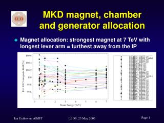
MKD magnet, chamber and generator allocation • Magnet allocation: strongest magnet at 7 TeV with longest lever arm = furthest away from the IP LBDS, 23 May 2006
MKD magnet allocation All calibrated magnets are within specification, so there is no reason not to install a specific magnet. As a result the two magnets which are the weakest at 7 TeV (MKD22 and MKD02) will be used as spare magnets. The strongest magnets are positioned at the positions 63_1 and 67_1. LBDS, 23 May 2006
MKD Chamber Allocation • No significant effect of the thickness of the coating on the rise time has been measured during the calibration • The thickness of the metallic coating has an effect on the delay between current and magnetic kick and on the kick strength. These two effects will need to be taken into account for the final adjustment of the system. • By not using the two chambers with the smallest impedance (chambers 8 and 9), the expected correction to be applied to the timing should be smaller than 30 ns. • As the chambers with the smallest impedance will not be used, the expected effect on the kick strength will be around 0.2 – 0.3 % while the effect on the current seems to be larger, around 0.5 %. LBDS, 23 May 2006
MKD Chamber Aperture • Chambers are sorted according to their measured physical aperture Aperture for D = 57 mm = specification Aperture for D = 59 mm= large fraction of chambers LBDS, 23 May 2006
Measured MKD ‘minimum’ apertures LBDS, 23 May 2006
Taking into account the two chambers used for MKQA, there will be 5 spare MKD chambers. To be able to use the spare chambers in all positions, three spare chambers with a diameter of 59.4 mm have been chosen, so if necessary they can also be used at the position furthest away from the IP. The chamber in the centre with the smallest diameter (d = 57.4 mm) will have an n1 = 7.7, which is always in the shade of the chamber initially installed at position 1, where d = 59.7mm results in n1= 7.2. LBDS, 23 May 2006
Calibration is not finished yet Rise time is critical Spec. = 2.8 μs Two different families, depending on the type of switches Mix the two types to get the smallest effective system rise time Generator Sorting LBDS, 23 May 2006
Generator Sorting • Electronics / control systems might be ‘identical’ • Wait for spread in calibration data • If not significant, can install control racks independent of Power Electronics • Independently: first choice of positioning of generators to be done in June = half of generators calibrated • Not clear on which parameters yet • Leaver arm? LBDS, 23 May 2006