DMA Transfer Modes in Data Storage
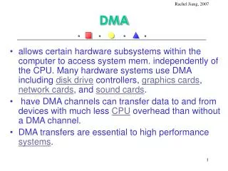
Learn how DMA (Direct Memory Access) and PIO (Programmed I/O) modes differ in data transfer speed and efficiency in IDE/ATA interfaces. Explore the benefits of Ultra DMA and the evolution of transfer rates.


DMA Transfer Modes in Data Storage
E N D
Presentation Transcript
Transfer Mode • The transfer mode describes the way in which the data moves from the hard disk through the interface (IDE/ATA) and to the memory. • For example, it tells how fast data is transferred or what device is in charge of the transfer. • There are two basic categories • PIO (Programmed I/O) Mode • The processor micro-manages data transfer • DMA (Direct Memory Access) Mode • The processor delegates data transfer
Programmed I/O (PIO) Modes • In the PIO category, the processor controls the data transfer. • There are various PIO modes which differ mainly by speed. • Through the early to mid-90s PIO was the standard way to transfer data to the hard disk. • The original ATA standards document defined the first three modes. • With ATA-2, two faster modes were introduced.
Standard PIO Modes 3.3 MB/s = 3.3 106 bytes / second = (2 bytes / 600 10-9 s) Two bytes are transferred every 600 nanoseconds.
External rates • The PIO rates on the previous slide are external rates meaning that they reflect the rate that data in the hard disk’s buffer/cache can be transferred. • Recall that access times to locate and read from a random sector are of the order of milliseconds. • Reading a sector (512 bytes) in 20 ms would correspond to a rate of 25 KB/s. • If one were not buffering and transferring consecutive data, the PIO mode rates would be sufficient. • But we do transfer buffered data and the PIO transfer rates are considered prohibitively slow by today’s standards.
PIO is too, too slow • PIO is slow in two ways: • One does not achieve the same data transfer rates as with Ultra DMA, which is the standard transfer mode used for IDE/ATA today. • Because the processor controls the details of the transfer in PIO, the processor is distracted from performing other tasks. • Despite its slowness, PIO is still around because: • PIO is simple (built into the BIOS so it does not require drivers). • Backward compatibility • Can be used as a backup when something goes wrong with DMA.
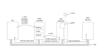
DMA • The alternative to PIO is DMA, Direct Memory Access. • In DMA, a device transfers information to or from the memory directly rather than in a processor-controlled fashion. • DMA has been around awhile but it was not always well supported early on. But speed requirements have made it preferred over PIO.
Various Modes • As with PIO, DMA has various modes differing mainly by speed. • DMA modes split into two categories: • Single-word modes which send one word (two bytes) at a time • Multiple-word modes which send several words in rapid succession (rather like the idea of bursting that accounts for improved memory speeds).
Assume it’s multiword • The single-word DMA modes are too slow, today it is understood that DMA is multiword DMA and the term is rarely mentioned and usually implied. • In fact, the single-word DMA modes were dropped from the standards with ATA-2. • Ultra DMA is multiword.
“The party of the first part shall be known in this contract as the party of the first part” First Party
First Party vs. Third Party • In Third-Party DMA there is a third device, the DMA controller mediating the transfer between the hard disk and memory. • Third party DMA is slow and old fashioned. • In First-Party DMA, a.k.a. bus mastering, the middle man is eliminated. The hard drive controls the transfer of data between itself and memory. • The device (hard drive in this case) takes control of (masters) the bus along which the information is sent.
Ultra DMA • DMA only became the norm with the introduction of Ultra DMA. • It just wasn’t well supported before. • DMA gained the advantage over PIO when Ultra DMA/33 doubled the interface transfer rate. • Support for it also improved. • Today, Ultra DMA is an industry standard.
Ultra DMA uses DDR and CRC • One feature that made Ultra DMA “ultra” was that it transferred data on both the positive and negative edges of the clock. • Same idea as in DDR (Double Data Rate) memory • As Ultra DMA pushed the limit on transfer rate, it made the occurrence of errors somewhat more likely. Thus it introduced a CRC (Cyclic Redundancy Check) as part of the standard. • Recall CRC is error detection. If an error occurs in transmission the data is retransmitted.
Ultra DMA transfer rates DMA finally beats PIO Mode 4’s 16.7 MB/s with the added bonus of freeing up the processor. The modes are usually named after their maximum transfer rate and the interface they use: Ultra ATA/100 instead of Ultra DMA/Mode 5.
New cable needed • The faster speeds did require a change in the cable used to connect the drive. The 80-conductor ATA/EDE cable. • Color Code • Blue: connects to the host (motherboard or controller). • Gray: connects to the slave drive (if there is one) • Black: connects to the master drive
80 wires and 40 pins?? • Signals are varying currents. • Currents produce magnetic fields, varying currents produce varying magnetic fields. • Varying magnetic fields produce currents. • Oops, the current in wire 1 begins to change the current in wire 2. • There is interference (a.k.a. cross talk) • The extra wires shield the signal-carrying wires from each other.
Block Mode • Certain BIOSs allow for a Block Mode setting. Block Mode allows 16 or 32 sectors (512 bytes each) to be handled using a single interrupt (even if the processor is not running the show it needs to know something has happened).
IRQs • Devices cannot interrupt the processor whenever they want. Instead they must request the processor’s attention. • Interrupt Request Numbers are an addressing scheme so that the processor can determine which device wanted its attention when when it gets around to checking for interrupts.
Resources • Many devices might want to interrupt the processor, so devices are assigned IRQs. • Usually this is done automatically. Occasionally two devices vie for the same slot and a conflict arises. • Devices other than the hard drive transfer information to or from memory and they use DMA as well. Devices are assigned ranges of memory they can use for DMA so as to avoid conflicts. • IRQs and DMA ranges are called system resources.
Viewing Resources for a Device Double click
ATAPI • The ATA/IDE Interface was originally designed for hard drives only. • AT Attachment Packet Interface (ATAPI) is a protocol that allows devices that are not hard drives to use this interface. • Instructions are sent to it in “packets”
Connecting a Hard Drive • There are typically three sets of pins and/or connectors associated with a hard drive • Power (Molex): the juice that allows it to operate • Data Interface: where data, addresses, instructions enter and leave • Jumper: switches that specify in what mode the drive will operate
Power Connectors The larger is the so-called Molex connector. The smaller is called the mini connector.
Two Categories • There are two basic categories of hard drives which have different interfaces. • IDE/ATA • ATA (Advanced Technology Attachment) is the formal name for IDE (Integrated Drive Electronics) is one of the standard interfaces between the motherboard and drives • SCSI: • Small Computer System Interface (“scuzzy”) is another interface particularly well suited for connecting many devices to
Different Interfaces/Different Connectors • IDE/ATA uses a 40-pin rectangular connector. • SCSI uses one of the following • 50-pin D-shaped connector (narrow SCSI) • 68-pin D-shaped connector (wide SCSI) • or 80-pin D-shaped connector (wide SCSI using single connector attachment (SCA))
Data Interface Connectors ATA/IDE SCSI
Serial ATA • The older, regular ATA is a parallel data connection, it is being replaced by serial ATA (SATA). • Similar to the USB port taking over roles previously played by the parallel port, the notion that serial connections are prohibitively slow has been overcome. • During this period of transition from a parallel ATA standard to a serial ATA standard, one has to be wary of compatibility issues.
SATA • The serial connection not only requires fewer wires (making it more flexible) but also allows those wires to be longer. • Also with fewer wires, there is less of a chance for crosstalk (interference). • SATA cables can be up to 1 m (39 in.) long. PATA ribbon cables, in comparison, carry either 40 or 80-conductor wires and are limited to 46 cm (18 in.) in length • PATA: Parallel Advanced Technology Attachment
SATA specifications • First-generation Serial ATA interfaces, also known as SATA/150, run at 1.5 gigahertz. • (3.0 Gbs with SATA 3Gb/s (sometimes known as SATA II) • This encoding scheme has an efficiency of 80%, resulting in an actual data transfer rate of 1.2 gigabits per second (Gbit/s), or 150 megabytes per second. • Following another trend, the SATA standard uses low voltages (specifically Low voltage differential signaling LVDS).
References • PC Hardware in a Nutshell (Thompson and Thompson) • http://www.pcguide.com • All-in-One A+ Certification, Meyers and Jernigan • http://www.webopedia.com • http://www.serialata.org • http://en.wikipedia.org/wiki/SATA