DMA CONTROLLER
DMA CONTROLLER. Md. Mojahidul Islam Lecturer Dept. of Computer Science & Engineering. Direct memory access:.


DMA CONTROLLER
E N D
Presentation Transcript
DMA CONTROLLER Md. Mojahidul Islam Lecturer Dept. of Computer Science & Engineering
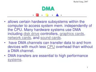
Direct memory access: • It transfers data directly between the RAM and an i/o device without involving the microprocessor. Using this technique the transfer of 1 byte of data typically requires 1 microsecond. DMA is extensively used in transferring large blocks of data between a peripheral device and the microcomputer memory.
BASIC DMA OPERATIONS: • Since DMA performs data transfer between memory and external device without involving the microprocessor the DMA interface or controller chip must be able to perform memory READ and WRITE operations in a similar way as the microprocessor. A DMA controller chip typically provides the following: • The DMA Controller chip puts the microprocessor in a HOLD state by means of the HOLD control signal. The microprocessor then stops executing the program and disconnects the address, data, and memory control lines form its bus by placing them in a high impedance state. • The DMA Controller chip takes over the microcomputer bus as soon as it receives the DMA acknowledge signal form the microprocessor. It puts the RAM location on the address bus and the appropriate control signal on the control bus in order to transfer data between the RAM and I/O device. • The DMA Controller chip controls all data transfer. After completion of data transfer, it transfer control of the system bus to the microcomputer by removing the microprocessor from the HOLD state.
TYPES OF DMA: • Two types of DMA controllers can be used to control the direct transfer of data between memory and several I/O devices: microprocessor halt DMA and interleaved DMA • Microprocessor halt DMA: In this type of DMA data transfer is performed between the memory and a peripheral device either by completely stopping the microprocessor until the transfer is completed or by a technique called cycle stealing. In either case, the microprocessor is stopped for DMA operation. The first method transfers a complete block of data and is therefore known as block transfer DMA. On the other hand with cycle stealing DMA data transfer occurs on a byte transfer basis until the transfer is completed. The decision of which type of DMA should be used depends on the length of the data block. If the data block is large block transfer is recommended. On the other hand for small data blocks cycle stealing DMA is used. Also if the microprocessor cannot be kept inactive in a particular application of the time needed for the block transfer cycle stealing DMA must be used. With either block transfer or cycle stealing a DMA controller chip controls the DMA operation. This chip typically consists of a register (containing the address of the data to be transferred to or from and a counter (containing the length of the data to be transferred. The address register is incremented by 1 each time a byte is transferred. Thus data is transferred in a sequential order. The counter containing the length of data is decremented by 1 each time a byte is transferred. When this counter is zero the DMA transfer is completed. The DMA controller is not independent of the microprocessor. The address register and the counter are normally loaded by the microprocessor.
TYPES OF DMA: • Block transfer DMA: This is the most common type of DMA used with microprocessors. In this type of DMA the peripheral device requests the DMA transfer via the DMA request line, which is connected directly or through a DMA controller chip to the microprocessor. The microprocessor completes the current instruction and sends a HOLD acknowledge to the DMA controller chip which in turn sends a DMA ACK signal to the I/O device in order to indicate that the bus can be used for DMA operation. The DMA controller chip then completes the DMA transfer and transfers the control of the bus to the microprocessor. Fig 1 shows a typical diagram of block transfer DMA. In fig 1 the I/O device requests the DMA transfer via the DMA request line connected to the DMA controller chip. In response to this request the DMA controller chip sends a HOLD signal to the microprocessor. The DMA controller chip then waits for the HOLD acknowledge (HLDA) signal from the microprocessor. On receipt of this HLDA the DMA controller chip sends a DMA ACK signal to the I/O device. The DMA controller then takes over the bus and controls data transfer between the Ram an I/O device. On completion of data transfer the controller chip returns the bus to the microprocessor by disabling the HOLD and DMA ACK signals The DMA controller chip usually has at least three registers that are normally selected by the controllers register select (RS) line. The three registers are an address registers a terminal count register and a status register. Both address and terminal count register are initialized by the CPU. The address register contains the starting address of data to be transferred and the terminal count register contains the desired block of data to be transferred. The status register contains information such as completion of the DMA transfer.
TYPES OF DMA: • Cycle stealing DMA: In this technique, the DMA controller transfers a byte of data between the memory and a peripheral device by stealing a clock cycle of the microprocessor. The DMA controller will complete the transfer by passing the microprocessor and generating proper signals to complete the transfer. Since the microprocessor is operated by an external clock it is quite simple to stop the microprocessor momentarily. This is accomplished by not providing the clock signal to the microprocessor. An INHIBIT signal is used for this purpose. This INHIBIT is normally HIGH and is logically ANDed with the system clock to generate the microprocessor clock. • Interleaved DMA: Interleaved DMA is a more complex type of DMA operation. Using this technique the DMA controller takes over the system bus when the microprocessor is not using it. For example the microprocessor does not use the bus when it performs internal operations such as decoding an instruction or ALU operations. The DMA controller takes advantages of those times in order to transfer data and this is called interleaved DMA. One of the main characteristics of interleaved DMA is that data transfer occurs without stopping the microprocessor. With interleaved DMA each data transfer includes 1 byte per instruction cycle.
Programmed I/O: • Using this method of I/O transfer the microprocessor communicates with an external device via an I/O port buffer commonly called an I/O port. These I/O ports are occasionally fabricated by the manufacturer in the same chip as the memory chip in order to achieve minimum chip count for small system applications. In other words a single chip will usually have both ROM and I/O or RAM and I/O. For example the intel 8155 contains 256 bytes of RAM and three I/O ports and 8355/8755 has 2k of ROM/EPROM with two I/O ports. • Standard I/O versus memory mapped I/O; There are two ways of addressing an I/O port: Standard and memory mapped I/O. The standard I/O typically utilizes a control pin onto the microprocessor chip commonly called the IO/M control signal. A HIGH on this pin indicated an I/O operation whereas a LOW indicated a memory operation. The execution of IN and OUT instructions sets IO/M to HIGH. If IO/M is output by the microprocessor in order to distinguish between I/O and memory operation then the microprocessor is said to utilize standard I/O. On the other hand if the microprocessor does not utilize the IO/M then the microprocessor does not differentiate between I/O and memory. In this case the microprocessor used RAM address to represent I/O ports and this is called memory mapped I/O.
Programmed I/O: • With standard I/O one typically uses 2 byte instructions name IN and OUT as follows: • IN XX(port number) it is 2 byte instruction for inputting data from specified port into accumulator. • OUT XX(port number) it is 2 byte instruction for outputting data from accumulator into specified port . • With memory mapped I/O one uses 3 byte instructions namely LDA and STA as follows: • LDA XXXX(I/O port address mapped into memory) it is 3 byte instruction for inputting a byte into accumulator . • STA XXXX(I/O port address mapped into memory) it is 3 byte instruction for outputting data from accumulator into specified port .
Programmed I/O: • Unconditional versus conditional programmed I/O: • In unconditional I/O, data transfer occurs at any time that is the external device must always be ready for data transfer. A typical example is that microprocessor outputs a 7 bit code via an I/O port in order to drive a seven segment LED display connected to this port. • With conditional I/O data transfer between the microprocessor and an external device occurs via handshaking that is the microprocessor executes a program in order to verify whether the external device is ready to transfer data. In this technique the microprocessor inputs the status of the external device and checks this status in order to determine whether the device is ready for data transfer. The microprocessor sends data to or receives data from the device when the device is ready. • Handshaking: The transfer of control information between the microprocessor and an external device is called handshaking.
Interrupt I/O: • Microprocessor can transfer data to or from an external device using the interrupt I/O. In order to accomplish this the microcomputer used a pin on the microprocessor chip called the interrupt pin (INT). The external I/O device is connected to this pin. When the device wants to communicate with the microcomputer it makes signal on the interrupt line HIGH or LOW depending on the microcomputer. • In response the microcomputer completes the instruction and pushes at least the contents of the current program counter and may be some other internal registers onto the stack. It then automatically loads an address into the program counter in order to branch to a subroutine like program written by the user. This program is called the interrupt service routine. It is a program that external device wants the microprocessor to execute in order to transfer data. The last instruction of the service routine is a RETURN instructions which is the same instruction typically used at the end of the subroutine. This instruction pops the address form the stack into the counter. The microcomputer then continues in the main program that it had been executing.
Interrupt I/O: • Interrupt types: External interrupts are usually initiated via the microcomputers interrupt pins by external devices such a s A/D converters. External interrupts can further be divided into two types. These are maskable and nonmaskable. A maskable interrupt can be enabled or disabled by executing instructions such as EI or DI. If the microcomputers interrupt is disabled the microcomputer ignores a maskable interrupt. Some processors such as the intel 8086 have an interrupt flag bit in the processor status register. When the interrupt is disabled the interrupt flag bit is set to 1 so that no maskable interrupts are recognized by by the processor. On the other hand the interrupt flag bit is reset to o when the interrupt is enabled. The nonmaskable interrupt has the highest priority over the maskable interrupt and cannot be enabled or disabled by instructions. This means that if both maskable and nonmaskable interrupts are activated at the same time then the processor will service the nonmaskable interrupt first. The nonmaskable interrupt is typically used as a power failure interrupt.
Interrupt I/O: • Internal interrupts are activated internally by exceptional conditions such as overflow, division by zero, and execution of an illegal OP code. Internal interrupts are handled in the same way as external interrupts. The user usually writes a service routine to take corrective measures and to provide an indication in order to inform the user that an exceptional condition has occurred. • Interrupt address vector: In order to service an interrupt the technique to find the starting address of the service routine (commonly known as the interrupt address vector) varies from one processor to another. With some processors the manufacturers define the fixed starting address for each interrupt. For some other processor the manufacturers use an indirect approach. They define fixed locations in which the interrupt address vector is stored.