Download
1 / 85
850 likes | 1.03k Vues
國立中央大學光電科學與工程學系 碩士學位論文口試. A Similarity-Guided Spots Sorting Method to Increase the Dynamic Range of a Shack Hartmann Sensor. Committee Dr. Chao-Wen Liang Dr. Yi-Chun Chen Dr. Chi-Hung Huang. Master’s Oral Defense 24 th July 2013 Phua Soo Fan. Outline. Introduction Literature Review

E N D
國立中央大學光電科學與工程學系 碩士學位論文口試 A Similarity-Guided Spots Sorting Method to Increase the Dynamic Range of a Shack Hartmann Sensor Committee Dr. Chao-Wen Liang Dr. Yi-Chun ChenDr. Chi-Hung Huang Master’s Oral Defense 24th July 2013 PhuaSoo Fan
Outline • Introduction • Literature Review • Methods • Results • Conclusion
Outline • Introduction • Working principle of Shack-Hartmann sensors • Spot Assignment, Dynamic Range • Motivation • Literature Review • Methods • Results • Conclusion
Working Principles • Transverse ray aberration VS. Wavefront
Analysis of SH Data • Spots Centroiding • Spots Assignment • Wavefront Reconstruction
Analysis of SH Data • Determining centroid of all spots • Identify spots • Thresholding • Determine spots’ centroid using the energy distribution • Spots Centroiding • Spots Assignment • Wavefront Reconstruction
Analysis of SH Data • Spots Centroiding • Spots Assignment • Wavefront Reconstruction • Assign SH spots to their lenslets
Analysis of SH Data • Spots Centroiding • Spots Assignment • Wavefront Reconstruction • Reconstruct wavefront from assigned spots • Zonal : Southwell integration • Modal : Zernike polynomials
Outline • Introduction • Working principle of Shack-Hartmann sensors • Spot Assignment, Dynamic Range • Motivation • Literature Review • Methods • Results • Conclusion
What is Sorting / Assignment? Assign spots to their corresponding lenslet Output from CCD + Centroiding
Conventional Sorting Algorithm • Spot shift < Lenslet diameter 2 spots Wrong spot Missing spot
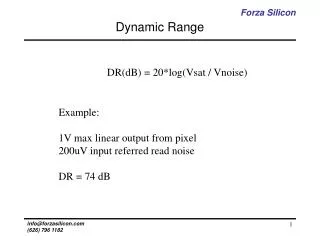
Dynamic Range • The maximum measurable wavefront slope • Focal length , Dynamic range d Long focal length Short focal length
Dynamic Range vs. Sensitivity • Sensitivity: • Focal length , Dynamic range , Sensitivity
Outline • Introduction • Working principle of Shack-Hartmann sensors • Spot Assignment, Dynamic Range • Motivation • Literature Review • Methods • Results • Conclusion
Conventional Syst. Configuration • System Aberration • Collimating Optic • Beam Expander
Conventional Syst. Configuration • System Aberration • Collimating optics are not perfect • Calibration is needed • Reference wavefront • Reference spots • Shifts from reference spots are taken as actual transverse ray aberration
Conventional Syst. Configuration • System Aberration • Collimating optics are not perfect • Calibration is needed • Reference wavefront • Reference spots • Shifts from reference spots are taken as actual transverse ray aberration Generating a reference wavefrontcan be difficult and expensive!
Conventional Syst. Configuration • System Aberration • Collimating optics are not perfect • Calibration is needed Not a once-and-for-all work Test Optic Additional aberration is introduced into the system Test Optic When lenses with different power are tested, beam expanders are needed - To fill the full CCD area
Proposed Configuration • SH system without collimating optics • Smaller system aberration • Calibration of lens array is required • Higher angle of incidence • Correction on off axis aberrations
Proposed Configuration • SH system without collimating optics • Smaller system aberration • Calibration of lens array is required • Measurement of negative lenses is not feasible • Effective area of CCD is decreased Drawback
Proposed Configuration • SH system without collimating optics • Smaller system aberration • Calibration of lens array is required • Measurement of negative lenses is not feasible • Effective area of CCD is decreased • Conventional assignment algorithm not feasible
Proposed Configuration • SH system without collimating optics • Smaller system aberration • Calibration of lens array is required • Measurement of negative lenses is not feasible • Effective area of CCD is decreased • Conventional assignment algorithm not feasible Motivation 1 New assignment algorithm is required!!
Spots’ Crossover • Spots crossover: When aberration is large Motivation 2 Expand dynamic range
Outline • Introduction • Working principle of Shack-Hartmann sensors • Spot Assignment, Dynamic Range • Motivation • Literature Review • Methods • Results • Conclusion
Outline • Introduction • Literature Review • Published Sorting Algorithm • Spiral • Spline Extrapolation • Zernike Extrapolation • Path of Assignment • Methods • Results • Conclusion
General Sorting Algorithms Initialization Obtain Assigned Spots Used to Various Prediction Methods! Predict Locations of Neighboring Spots While unassigned spots ~= 0 Assign closest spots within search region
Spiral • Linear prediction • Prediction basis: 3 spots • Fourth spot forms a parallelogram with the 3 spots
Outline • Introduction • Literature Review • Published Sorting Algorithm • Spiral • Spline Extrapolation • Zernike Extrapolation • Path of Assignment • Methods • Results • Conclusion
Path of Assignment • All published methods follow a pre-determined path, as shown in the video below.
Predetermined Path vs. Guided Path • Predetermined path: • New spots predicted using assigned spots • Error propagation • Guided • Quality map • Spots with higher quality indicator • Assign with higher priority • Avoid error propagation
Outline • Introduction • Literature Review • Published Sorting Algorithm • Spiral • Spline Extrapolation • Zernike Extrapolation • Path of Assignment • Methods • Results • Conclusion
Outline • Introduction • Literature Review • Methods • Quality Map • Linear Assignment • Priority Buffer • NonLinear Assignment • Results • Conclusion
Quality Map • How to determine the quality of spots? • A parameter to identify the quality is required!
Quality Map Low DAP = High quality Initialization Quality Parameter, DAP Obtain Assigned Spots Used to There’s a DIFFERENCE in predicted location and the exact spot location Predict Locations of Neighboring Spots While unassigned spots ~= 0 Assign the closest spot within search region
Location Prediction Initialization Obtain Assigned Spots Used to Predict Locations of Neighboring Spots While unassigned spots ~= 0 Assign the closest spot within search region
Location Prediction • Linear • Fast • Incapable of handling spots crossover • Applied to central region • Non-Linear • Slow • Able to predict crossover positions • Applied to outer region
Outline • Introduction • Literature Review • Methods • Quality Map • Linear Assignment • Priority Buffer • NonLinear Assignment • Results • Conclusion
Linear Assignment Newly-assigned spot, Prediction base
Outline • Introduction • Literature Review • Methods • Quality Map • Linear Assignment • Priority Buffer • NonLinear Assignment • Results • Conclusion
Priority Buffer Initialization: 4 spots assigned (‘X’) Spots 5,6,7 and 8 predicted, inserted into Buffer Spots 1,2,3 and 4 predicted, inserted into Buffer Buffer arranged, Spot 3 assigned Arranged accord. To DAP Spot #1 assigned
Outline • Introduction • Literature Review • Methods • Quality Map • Linear Assignment • Priority Buffer • NonLinear Assignment • Results • Conclusion
Non Linear Assignment • Major slope directions (-45, 0, 45, 90) • Direction closest to Slope • Minor slope directions • The two other directions which are not perpendicular to major slope direction
Non Linear Assignment • Major slope directions (-45, 0, 45, 90) • Direction closest to Slope • Minor slope directions • The two other directions which are not perpendicular to major slope direction
Non Linear Assignment • Major slope directions (-45, 0, 45, 90) • Direction closest to Slope • Minor slope directions • The two other directions which are not perpendicular to major slope direction
Prediction Base • Primary base • The newly-assigned spot • Secondary base • Assigned neighbors of primary base Secondary base
Prediction Basis • Comprises of the base + 2 assigned neighbors • Formed along slope directions Predicted spot Minor slope direction Major slope direction Minor slope direction
Prediction Basis • Repeated on every secondary base Predicted spot Minor slope direction Major slope direction Minor slope direction