Download
1 / 35
610 likes | 2.31k Vues
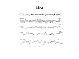
Calibration of Digital EEG machines. Mark Stevenson. Calibrate. Mark with scale of readings Correlate reading of instrument with standard Adjust accordingly. Why Calibrate an EEG machine. Correct representation of EEG signal EEG machines are multi-channel

E N D
Calibration of Digital EEG machines Mark Stevenson
Calibrate • Mark with scale of readings • Correlate reading of instrument with standard • Adjust accordingly
Why Calibrate an EEG machine • Correct representation of EEG signal • EEG machines are multi-channel • The recording characteristics must be the same for each channel/amplifier • This allows comparison between channels for • Amplitude • Frequency • Each channel/amplifier must respond at the same instance in time to the EEG signal to allow • Time relationships between channels to be studied
Machine check for EP/EMG machines Disc space My computer Click on hard disc drive
Machine check for EP/EMG machines Time and Date My computer Control panel Time/date
Sensitivity • The sensitivity of a system is the magnitude of input voltage required to produce a standard deflection in the recorded trace • Measured in microvolts per centimetre (Vcm-1) or microvolts per millimetre (Vmm-1) • Routine EEG sensitivity is usually 70 -100 Vcm-1
Sensitivity Sensitivity may be checked before each recording using the internally generated square wave and measuring the voltage using the measurement cursors
Linearity • A recording channel is said to be linear if the output deflection is proportional to the amplitude of the input signal at a constant sensitivity
Linearity • Linearity can be checked by injecting a series of square wave pulses of decreasing amplitude at a constant sensitivity • The calibration pulse amplitude can the be plotted against the output deflection (see graph)
Analogue EEG Machine With an analogue machine the montaging was at the amplifier input. If you wanted to connect the same two electrodes to each amplifier it was possible. You could therefore perform a ‘biological calibration’ or ‘all channel check’.
Digital EEG Machine With a digital machine each electrode has it own amplifier and montaging is performed at the amplifiers outputs.
Equipment Connections The way montaging is performed in the digital machine has implications when we want to apply an external calibration signal, as we want the same signal on all channels. EPTA commissioned a firm to produce a box which allowed the same signal to be applied to each channel and to attenuate a signal from a signal generator into the micro-Volt rage.
External calibration unit(SNS/EPTA ATTENUATOR) Used with a signal generator
External calibration unit(WAVEFORM GENERATOR) Minimum Specification for External Signal Generator • Frequency Range 0.1-200Hz • Frequency accuracy ±1% of full scale • Amplitude accuracy ±5% on 0.5 volt pk to pk range • Sinusoidal distortion less than 0.5% • Square wave mark-space ratio 1:1±1% • Output impedance 50Ω
Calibration or ?Machine check(Digital machine) Signal generator • Using an external signal generator the machine can also check • Sensitivity • Linearity • Step gain control • Frequency response • Noise • CMRR Head box Digital EEG machine Display
EPTA GUIDELINES FOR CHECKING DIGITAL EEG MACHINES AT EACH RECORDING • Visually check cables, check enough disc/recording space and check correct date and time. • Apply and record an internal calibration signal and visually check sensitivity, display alignment and appearance of filters • Measure electrode impedances and record them. • Select referential/acquisition montage and record. (It is recommended that this montage is often checked again during the recording and at the end of recording) • When reviewing, again check recorded internal calibration signal at the reader station.
EPTA GUIDELINES FOR CHECKING DIGITAL EEG MACHINES EVERY THREE MONTHS • Check physical condition of whole system, recorder, reader and server. Check cables, head-box, network points, printer, keyboard, and cable connections. • Perform housekeeping : check default settings, delete unwanted montages, ensure ECG and photic selections are correct, delete unwanted word files, complete archiving. • Using the external signal generator check the following at recorder and check at reader: • Sensitivity • Step sensitivity (constant input, change sensitivity) • Amplitude linearity (constant sensitivity, change input) • Display Speed • Noise • Accuracy of montages • Filters. • Check the photic stimulator marker
EPTA GUIDELINES FOR CHECKING DIGITAL EEG MACHINES NEW MACHINE OR SOFTWARE UP-DATE • Perform the three month check, and in addition, using the external signal generator, check at recorder and reader: • Full frequency response graph • Common Mode Rejection Ratio
Display speed • Can be checked using a known frequency external signal • Calibrated signal generator. • 50Hz
Frequency response • The relationship between sensitivity and frequency, of a system is represented by the FREQUENCY CHARACTERISTICS • This characteristic may be obtained by applying sine waves of constant voltage but varying frequency to the input of a system and measuring the voltage at its output
Noise • Noise is inherent in the machine and is produced by thermal movement of electrons • The noise is of different frequencies, mostly high • The noise level of an EEG machine should not exceed 2V at a high frequency cut off of 70Hz 700 Hz 70 Hz
Common mode rejection ratio(CMRR) • The gain of a differential amplifier is much greater for anti-phase signals (differential) than for in-phase signals ((common mode) • Ratio of these two amplifications is called the common mode rejection ratio (CMMR) or discrimination ratio • The larger the ratio, the greater the rejection of the common mode signal (external interference)
Common mode rejection ratio(CMRR) • Common mode rejection ratio = differential gain Common mode gain • Common mode rejection ratio referred to in decibels (dB) • dB = 20Log10(CMRR) • Common mode rejection ratios • 50:1 34dB • 100:1 40dB • 500:1 54dB • 1000:1 60dB • 5000:1 74dB • 10,000:1 80dB • 50,000:1 94dB • 100,000:1 100dB
Measurement of CMRR • External calibrator • 10Hz sine wave 100V pk to pk applied to the input • Sensitivity adjusted to give a known deflection on screen (eg 10mm) • Input leads shorted together and external calibrator connected between them and earth • External calibrator voltage increased until same deflection (of 10mm) is obtained on the screen • Ratio between voltage necessary to achieve this and 100V is the CMRR
Measurement of CMRR • If signal required to give 10mm output is 920mV or 920000V • Then the • CMRR = 920000V • 100V • In dB • CMRR =20(Log10(9200)) • =80dB 10Hz sine wave 100V pk topk Output 10mm Head box 10Hz sine wave Increase voltage To XV To produce 10mm Output Head box Earth
Aliasing check Input=10 Hz 10 Hz
Aliasing check Input=50 Hz 50 Hz
Aliasing check Input=70 Hz 70 Hz
Function of photic stimulator • On digital machines, if the photic stimulator is driven by the machine, a mark will appear on the screen each time the photic stimulator is triggered. If there is a fault with the stimulator itself or the bulb the light may not flash or may only do so intermittently, this may be obvious at slow rate but not at high rates. It is suggested therefore that the function of the photic stimulator is checked using a photocell .