HVDC Challenges and Operation in Grid by V.G. Rao
640 likes | 804 Vues
Learn about the operation challenges and control mechanisms of HVDC systems at Kolar and Talcher stations. Explore the reactive power control modes and stability functions.

HVDC Challenges and Operation in Grid by V.G. Rao
E N D
Presentation Transcript
WELCOME HVDC Challenges in Grid Operation By V.G.Rao Chief Manager HVDC Kolar
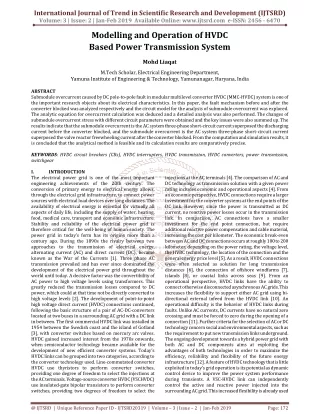
TALCHER KOLAR SCHEMATIC TALCHER Electrode Station Electrode Station KOLAR +/- 500 KV DC line 1370 KM Kolar 400kv System 220kv system Hosur Hoody B’lore Chintamani Salem Madras Cudappah Udumalpet
Points related to operation of HVDC • RPC control • Filter switching seq. • Limitations by RPC • Stability Controls • Power Limitations • Frequency limit controller • Run-backs / Run-ups • Power Swing damping control • GRM operation & electrode limitation • Overload of HVDC • SPS scheme • Power / current limits due to protection • Power reversal
Reactive power control / RPC : 2 modes • Q- mode – Reactive Power control mode – • The switching limit for the filter can be adjusted by entering the maximum set value of Reactive power (Q) by the operator. • Possibility to select between Q-basic or Q-extended mode • Max limit for Q-basic: Talcher - +100MVAr, Kolar - +500MVAr • Max limit for Q-extended: Talcher - +500MVAr, Kolar - +500MVAr
Reactive power control / RPC : 2 modes • U-mode – Voltage control mode • The switching limit for the filter can be adjusted by a maximum and minimum set values of AC bus Voltage. • is maintained. • If the voltage of the bus reaches the minimum limit, filter will be switched into service. • If the voltage of the bus reaches the maximum limit, filter will be switched out of service • Upper limit : Talcher / Kolar 440kV • Lower limit : Talcher / Kolar 360kV • Bandwidth of 20KV
Reactive Power Control • Reactive Power Control is mainly achieved by switching individual reactive power sub banks • Provided Reactive Power Sub Banks - Kolar Double tuned 12/24 harmonic (type A) – 8 no’s- 120MVAr each Double tuned 3/36 harmonic (type B) – 4 no’s- 97MVAr each Shunt capacitor sub-bank (type C) – 5 no’s – 138MVAr each • Provided Reactive Power Sub Banks - Talcher Double tuned 12/24 harmonic (type A) – 7 no’s- 120MVAr each Double tuned 3/36 harmonic (type B) – 4 no’s- 97MVAr each Shunt reactors (type L) – 2 no’s – 80MVAr each Shunt capacitor sub-bank (type C) -1 no. -66MVAr
Reactive Power Control • Switching ON criteria of individual sub banks and their hierarchy: • sub bank switching according to Harmonic Performance – given higher priority and depends on actual DC power flow • AC bus bar voltage within operator reference values – if RPC is in U-mode – next priority • total station reactive power within operator reference values – if RPC is in Q-mode – next priority • Switching OFF criteria of individual sub banks and their hierarchy: • Sub banks switches out based on the AC bar voltage only
Filter Switching settings for Kolar Bipolar operation -100% DC voltage Bipolar operation -80% DC voltage
Filter Switching settings for Kolar Monopolar operation -100% DC voltage Monopolar operation -80% DC voltage
Reactive Power Control • Manual control of sub banks is possible by the operator • AC voltage limitation is permanently active irrespective of manual / automatic switching of filters • CONNECT INHIBIT level – filters/shunt-c cannot be connected in manaul /auto • AC bus voltage is above 431kV ( reset at 424kV) or • Reactive power export to the grid is high compared to active power (refer table) • ISOLATE level - filter sub banks/ shunt C are switched OFF in 0.5 seconds interval automatically at 440kV • ISOLATE INHIBIT - Switching off of sub-banks is blocked if the AC voltage drops below 380kV • CONNECT limit - additional banks will be switched on (in 1 second interval) automatically if the AC voltage reaches 360kV
RPC sub bank connect inhibit levels At Connect Inhibit level – Control system prevents switching ON of filters / shunt C in auto or manual irrespective of AC voltage to prevent export of excessive reactive power
STABILITY FUNCTIONS • Power Limitations • Always enabled in the control system • Becomes active once the AC switchyard configuration for NTPC at Talcher or 400kV S/y at Kolar changes- refer tables • Introduced to improve stability in the regions, self excitation of generators, failure of control systems etc. • Power capability depends upon the no. of generators / lines connected to HVDC • Automatic limitation of power takes place
POWER LIMITATIONS-TALCHER • Two lines / one pair of lines equivalent to 500MW • If all the generators at Talcher trips / only lines are considered for power limitation
STABILITY FUNCTIONS • Frequency limit controller • Stability functions needs to be enabled by the operator • FLC comes into action if the frequency limits are set within a band of current frequency • Enabled automatically during islanding or split bus mode at Talcher • Enabled automatically during split bus mode at Kolar • Can be enabled individually at Talcher or Kolar • If telecom is faulty – FLC of Kolar is disabled auotmatically
STABILITY FUNCTIONS • Run-backs / Run-ups • If stability functions are enabled, these functions are automatically enabled • At present this functions are not programmed • Automatic ramping up of power is possible with certain conditions • 5 conditions can be programmed / hardware inputs • Automatic ramping down of power is possible with certain conditions • 5 conditions can be programmed / hardware inputs • Individual run ups/run backs can be enabled or disabled for Talcher/Kolar station
STABILITY FUNCTIONS • Power Swing damping control • Stability functions are to be enabled & power swing damping function to be enabled • Power Swing Damping function provides positive damping to the power flow in the parallel AC system • This function becomes active automatically during emergency conditions or major disturbance of the AC system • Additional DC power is calculated based on the frequency variation / swing of the connected AC system • This function is provided for each pole at each station
Current Current Modes of Operation Bipolar Smoothing Reactor DC OH Line Smoothing Reactor Thyristor Valves Thyristor Valves Converter Transformer Converter Transformer 400 kV AC Bus 400 kV AC Bus AC Filters, Reactors AC Filters, shunt capacitors
Current Modes of Operation Monopolar Ground Return Smoothing Reactor DC OH Line Smoothing Reactor Thyristor Valves Thyristor Valves Converter Transformer Converter Transformer 400 kV AC Bus 400 kV AC Bus AC Filters, Reactors AC Filters
Current Modes of Operation Monopolar Metallic Return Smoothing Reactor DC OH Line Smoothing Reactor Thyristor Valves Thyristor Valves Converter Transformer Converter Transformer 400 kV AC Bus 400 kV AC Bus AC Filters, Reactors AC Filters
Automatic MR-GR changeover • Normal operation – Balanced Bipolar operation • When one pole trips, healthy pole goes to Ground Return mode • Limitation in Kolar electrode • Healthy pole goes to Metallic Return mode automatically – power flow restricted to 1000MW • Operator can increase the power manually to the overload capability of the healthy Pole after one Pole trips
Automatic MR-GR changeover • If line fault / failure of Metallic return changeover healthy Pole remains in GR mode • Changeover from GR mode to MR mode takes around 75secs • Failure of changeover may be due to problems in the DC switches or tele-control failure • If all Blocking devices are healthy power flow settles at 500MW in GR mode • If any Blocking device faulty power flow settles at 150MW • Operator can set the 150MW limit / 500MW limit manually if required • During the automatic seq. process power flow follows the defined curve as shown • At present 150MW limit is set in GR mode
UPGRADATION OF HVDC PROJECT - PURPOSE • Outage of 400 kV transmission lines from Talcher that requires transmission of maximum power over this link • Outage of one Pole which requires maximum possible transmission of power on the other pole continuously in metallic return mode due to the restrictions in the GR mode at Kolar
Basic Components of HVDC Terminal Converter Xmers DC Line Smoothing Reactor 400 kV AC PLC DC Filter AC Filter Valve Halls -Thyristors -Firing ckts -Cooling ckt -Control & Protection -Telecommunication Control Room
UPGRADATION OF HVDC PROJECT - HIGHLIGHTS • Existing overload capacity of the equipment being used for long time loads – The overload characteristics of HVDC are modified in Upgrade • All the equipment ratings were studied and critical equipment has been identified for modifications • Smoothing Reactor, Converter Transformer, LVDC bushing and PLC reactors (at Kolar) requires additional modifications / replacement • Relative ageing of the critical eqpt.- Converter Transformer and Smoothing reactor are being monitored in real time
New Over load features of HVDC The overload under upgradation is only long time loading of HVDC but not the continuous loading under which HVDC can operate at 1.25 p.u for max. of 10 hrs in a day while the rest of the day at 1.0p.u at ambient <40ºC
Over load features of HVDC • It is permissible to apply the half-hour overload once in every 12 hour period • The five second overload remains unchanged -1470MW • It is permissible to apply the five second overload power once in a five minute period and up to at least 5 times during a two hour period • The five second overload can be applied during operation at the long time overload or half an hour overload. • With Telecom out of service above overloads are not applicable
Long time limits with redundant coolingat normal & extreme AC bus voltages at Kolar
Half-hour limits with redundant coolingat normal & extreme AC bus voltages at Kolar
Extended long time limitwith redundant Coolingfor extreme ac voltage range
Half hour limitwith redundant Coolingfor extreme ac voltage range
Smoothing Reactor • Hot spot temperature of the insulation to be within limits at new extended overload • The extended overload is achieved without sacrificing the designed life of the Smoothing reactor • Forced air cooling ducts are installed to keep the hot spot temperature within limits • Overload capacity is monitored by using Relative Ageing Indication (RAI) and Load Factor Limitation (LFL) • The status of the SMR forced cooling system decides the overload limits of the system • The SMR cooling will be automatically switched ON if the DC current is >1950A and the ambient temperature is >28 ºC
DEFENCE MECHANISM FOR SR Operational from March 2006 • Based on absolute power • Power loss being calculated as • Loss = Power 2 Secs prior to trip – Power after trip • Tripping due to line fault is considered – since during LF, healthy pole power is limited to 150MW in GR mode • Signals transmitted through FO instead of PLCC • Separate protection couplers installed
DEFENCE MECHANISM FOR SR Trip generation LOGIC • Condition 1: • (500MW<Power loss ≤1000MW) & Pole Block = TRIP I • Condition 2: • (1000MW<Power flow ≤1500MW) & Line fault & Pole Block = TRIP I • Condition 3: • (Power loss >1000MW) & Pole Block = TRIP II • Condition 4: • (Power flow >1500MW) & Line fault & Pole Block = TRIP II Whenever Trip II is generated, Trip I also generates
Power Power Power P 1 P 1 P 1 PLC PLC PLC HVAC PLCC HVAC PLCC HVAC PLCC Block Block Block Protection couplers Protection couplers Protection couplers Deblock Deblock Deblock Line fault Line fault Line fault Protection couplers Protection couplers Protection couplers Power Power Power P 2 P 2 P 2 SER SER SER Block Block Block Deblock Deblock Deblock Fault Recorder Fault Recorder Fault Recorder Line fault Line fault Line fault BLOCK DIAGRAM OF DEFENCE MECHANISM FOR SR TRIP I TRIP II
DEFENCE MECHANISM FOR SR Load relief: TRIP I Trip I Andhra Pradesh Chinakampalli 150MW Kolar Chintamani Hoody Karnataka 250MW Hosur Sriperambudur Selam Tamil Nadu 300MW
DEFENCE MECHANISM FOR SR Load relief: TRIP II Trip II Gooty Anantapur Somayajulapalli Kurnool Andhra Pradesh 200MW Karnataka Somanahalli 200MW Madurai Karaikudi Thiruvarur Trichy Ingur Tamil Nadu 200MW Kerala Trichur Kozhikode Kannur 200MW
Recent cases of SPS non-operation • The system has worked perfectly in all cases and saved the SR grid • Some improvements are being done in following cases • Pole 2 trip on 11.06.2010 • Problem in the Pole control system selection • DC power was around 700MW and Pole 1 has taken over the power immediately after tripping • Hence inter trip signal need not be generated. • Pole 2 trip on 19.08.2010 • Problem in the Pole control system selection • The power loss was >500MW • Inter trip signal was not generated in this case • Since both Pole control system 1 &2 of Pole 2 had failed, the Pole Block signal was not transmitted by the Pole control to the defence mechanism • This in turn could not generate the inter trip signal though the power loss was sufficient for the signal generation.
Proposed modification • Pole control system generates ESOF (Emergency Switch OFF) signal to DC protection & SER • This signal is available even during the complete power supply failure in both the Pole controls • One more Binary input for the detection of the Pole trip in the above cases from each Pole • This signal can be used with OR logic for the existing Block /Deblock logic for Pole 1 & 2 • Additionally 2 relays have to be installed in Pole Control and logic modification has to be carriedout.
PLC Power P 2 Block Deblock Line fault Power P 1 HVAC PLCC Block Protection couplers Deblock Line fault Protection couplers "ESOF" SER Fault Recorder Proposed addition of I/O signals "ESOF"
Trip signal -3 • Addition of Trip signal-3 : Trip signal 3 will be initiated • Any one pole / both poles block AND Power loss compared with power flow 2 secs prior to Pole block is >2000MW • OR • If one of the pole block on line fault AND Power flow just prior to that instant was >2000MW • List of DTPCs to be wired for the load relief of 500MW for trip signal -3 has to be provided by SRLDC. The S/w and H/w modifications in the PLC & DTPC panels will be carriedout at HVDC Kolar.
Trip Signal-2 • Modified logic: • Any one pole / both poles block AND Power loss compared with power flow 2 secs prior to Pole block is >1000MW and less than or equal to 2000MW • OR • If one of the pole block on line fault AND Power flow just prior to that instant was >1500MW and less than or equal to 2000MW.
Trip-1&2 during trip-3 Generation of Trip 1 & Trip 2 signals when Trip 3 is generated: Modifications will be carriedout at HVDC Kolar as per the desired logic.
Trip signal on Line fault • Generation of trip signal on Line fault: SRLDC has suggested following solutions to overcome the problem with inter trip signal on line fault. • Generate trip signals -2 after 3 re-tries if set point is >1500MW:The number of retries may vary depending upon the generator / line condition at Talcher. Hence, this logic may fail in some cases. • Generate trip signal -2 if (original set point – Current power flow) exceeds 1500MW in a minute interval: For measuring the power flow 2 secs prior to the Block signal, at present 10 samples for every 200msec are being considered. For 2 minutes we have to take 300 samples and the PLC may hang.