HVDC
HVDC. Report Submission. Description of contribution by each member in the group before the introduction chapter Ensure that all references are according to IEEE standards

HVDC
E N D
Presentation Transcript
Report Submission • Description of contribution by each member in the group before the introduction chapter • Ensure that all references are according to IEEE standards • The report should clearly demonstrate the contribution of the group in the given topic of project and should NOT be merely collection of information from other references • The grading of the report will mainly depend on this
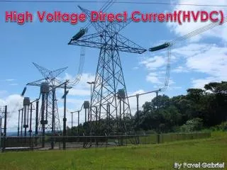
History • First commercial application of HVDC between Swedish mainland and the island of Gotland in 1954. • Underwater link of 90 km and 20 MW. • After the advent of thyristorconvertor, New Brunswick and Quebec 320 MW back-to-back DC interconnection commissioned in 1972. • With reduced size, cost and improved reliability of power electronic converters, has made HVDC transmission more widespread. • In North America, total HVDC transmission capacity in 1987 was 14,000 MW.
Advantages • In a number of applications HVDC is more effective than AC transmission. Examples include: • Undersea cables, where high capacitance causes additional AC losses. (e.g. 250 km Baltic Cable between Sweden and Germany) • Long power transmission without intermediate taps, for example, in remote areas • Power transmission and stabilization between unsynchronized AC distribution systems • Connecting a remote generating plant to the distribution grid • Reducing line cost: 1) fewer conductors 2) thinner conductors since HVDC does not suffer from the skin effect • Facilitate power transmission between different countries that use AC at differing voltages and/or frequencies • Synchronize AC produced by renewable energy sources
Disadvantages • The disadvantages of HVDC are in conversion, switching and control. • Expensive inverters with limited overload capacity • Higher losses in static inverters at smaller transmission distances • The cost of the inverters may not be offset by reductions in line construction cost and lower line loss. • High voltage DC circuit breakers are difficult to build because some mechanism must be included in the circuit breaker to force current to zero, otherwise arcing and contact wear would be too great to allow reliable switching.
Cost of HVDC Transmission • Costs vary widely depending on power rating, circuit length, overhead vs. underwater route, land costs, and AC network improvements required at either terminal. • For example, for an 8 GW, 40 km link laid under the English Channel, the following are approximate primary equipment costs for a 2 GW, 500 kV bipolar conventional HVDC link is: • Converter stations ~$170 M • Subsea cable + installation ~$1.5 M/km • So for an 8 GW capacity between England and France in four links, little change is left from ~$1.2B for the installed works. Add another $300–$450M for the other works depending on additional onshore works required
HVDC System Configurations and Components HVDC links can be broadly classified into: • Monopolar links • Bipolar links • Homopolar links • Back-to-back links • Multiterminal links
Monopolar Links • It uses one conductor • The return path is provided by ground or water • Use of this system is mainly due to cost considerations • A metallic return may be used where earth resistivity is too high • This configuration type is the first step towards a bipolar link
Bipolar Links • It uses two conductors, one positive and the other negative • Each terminal has two converters of equal rated voltage, connected in series on the DC side • The junctions between the converters is grounded • Currents in the two poles are equal and there is no ground current • If one pole is isolated due to fault, the other pole can operate with ground and carry half the rated load (or more using overload capabilities of its converter line)
Homopolar Links • It has two or more conductors all having the same polarity, usually negative • Since the corona effect in DC transmission lines is less for negative polarity, homopolar link is usually operated with negative polarity • The return path for such a system is through ground
Components of HVDC Transmission Systems • Converters • Smoothing reactors • Harmonic filters • Reactive power supplies • Electrodes • DC lines • AC circuit breakers
Components of HVDC Transmission Systems Converters • They perform AC/DC and DC/AC conversion • They consist of valve bridges and transformers • Valve bridge consists of high voltage valves connected in a 6-pulse or 12-pulse arrangement • The transformers are ungrounded such that the DC system will be able to establish its own reference to ground Smoothing reactors • They are high reactors with inductance as high as 1 H in series with each pole • They serve the following: • They decrease harmonics in voltages and currents in DC lines • They prevent commutation failures in inverters • Prevent current from being discontinuous for light loads Harmonic filters • Converters generate harmonics in voltages and currents. These harmonics may cause overheating of capacitors and nearby generators and interference with telecommunication systems • Harmonic filters are used to mitigate these harmonics
Components of HVDC Transmission Systems contd. Reactive power supplies • Under steady state condition conditions, the reactive power consumed by the converter is about 50% of the active power transferred • Under transient conditions it could be much higher • Reactive power is, therefore, provided near the converters • For a strong AC power system, this reactive power is provided by a shunt capacitor Electrodes • Electrodes are conductors that provide connection to the earth for neutral. They have large surface to minimize current densities and surface voltage gradients DC lines • They may be overhead lines or cables • DC lines are very similar to AC lines AC circuit breakers • They used to clear faults in the transformer and for taking the DC link out of service • They are not used for clearing DC faults • DC faults are cleared by converter control more rapidly
Multiple Bridge Converters • Two or more bridges are connected in series to obtain as a high a direct voltage as required • These bridges are series on the DC side, parallel on the AC side • A bank of transformers is connected between the AC source and the bridges • The ratio of the transformers are adjustable under load • Multiple bridge converters are used in even numbers and arranged in pairs for 12-pulse arrangement
Multiple Bridge Converters • Two banks of transformers, one connected in Y-Y and the other Y- are used to supply each pair of bridges • The three-phase voltage supplied at one bridge is displaced from the other by 30 degrees • These AC wave shapes for the two bridges add up to produce a wave shape that is more sinusoidal than the current waves of each of the 6-pulse bridges • This 12-pulse arrangement effectively eliminates 5th and 7th harmonics on the AC side. This reduces the cost of harmonic filters • This arrangement also reduces ripple in the DC voltage
Control of HVDC Systems • Objectives of Control • Efficient and stable operation • Maximum flexibility of power control without compromising the safety of equipment • Content • Principle of operation of various control systems • Implementation and their performance during normal and abnormal system conditions
Basic principles of control Direct current from the rectifier to the inverter Power at the rectifier terminal Power at the inverter terminal
Basic means of control • Internal voltages, Vdorcos and Vdoicos, can used be controlled to control the voltages at any point on the line and the current flow (power) • This can be accomplished by: • Controlling firing angles of the rectifier and inverter (for fast action) • Changing taps on the transformers on the AC side (slow response) • Power reversal is obtained by reversal of polarity of direct voltages at both ends
Basis for selection of control • Following considerations influence the selection of control characteristics: • Prevention of large fluctuation in DC voltage/current due to variation In AC side voltage • Maintaining direct voltage near rated value • Power factor at the receiving and sending ends should be as high as possible
Control implementation • Tap changer control • It is used to keep the converter firing angles ( and ) within the desired range • They are sized to allow for minimum and maximum steady state voltage variation • Current limits: • Maximum short circuit current is limited to 1.2 to 1.3 times normal full load current to avoid thermal damage to equipment • Minimum current limit is set to avoid ripple in the current that may cause it to be discontinuous or intermittent • Minimum firing angle limit: • In case of a DC fault, the inverter station may switch to rectification mode. This would result in reversal of power flow • To prevent this, the a minimum value for firing angle is set
Control implementation • Power control • To transmit a scheduled power, the corresponding current order is determined by: Iord=Po/Vd • Bridge/converter unit control • Determines firing angles and sets their limits • Pole control • It coordinates the conversion of current order to a firing angle order, tap changer control and other protection sequences
Multiterminal HVDC network • Successful application of two-terminal DC systems led to the development of multi-terminal networks • There are two possible connection schemes for MTDC systems: • Constant voltage parallel scheme • Constant current series scheme