Download
1 / 6
70 likes | 113 Vues
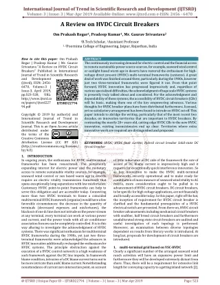
he continuously increasing demand for electric control and the financial access to remote sustainable power source sources, for example, seaward wind control or sunlight based warm age in deserts have restored the enthusiasm for high voltage direct present HVDC multi terminal frameworks systems . A great deal of work was finished around there, particularly during the 1980s, however just two three terminal frameworks were figured it out. From that point forward, HVDC innovation has progressed impressively and, regardless of various specialized difficulties, the acknowledgment of huge scale HVDC systems is presently truly talked about and considered. For the acknowledgment and dependability of these systems, the accessibility of HVDC circuit breakers CBs will be basic, making them one of the key empowering advances. Various thoughts for HVDC breaker plans have been distributed furthermore, licensed, yet no satisfactory arrangement has been found to intrude on HVDC cut off. This paper intends to abridge the writing, particularly that of the most recent two decades, on innovation territories that are important to HVDC breakers. By contrasting the mostly 20 years old, cutting edge HVDC CBs to the new HVDC innovation, existing inconsistencies end up clear. Territories where extra innovative work are required are distinguished and proposed. Om Prakash Regar | Pradeep Kumar | Mr. Gaurav Srivastava "A Review on HVDC Circuit Breakers" Published in International Journal of Trend in Scientific Research and Development (ijtsrd), ISSN: 2456-6470, Volume-3 | Issue-3 , April 2019, URL: https://www.ijtsrd.com/papers/ijtsrd22794.pdf Paper URL: https://www.ijtsrd.com/engineering/electrical-engineering/22794/a-review-on-hvdc-circuit-breakers/om-prakash-regar<br>

E N D
International Journal of Trend in Scientific Research and Development (IJTSRD) Volume: 3 | Issue: 3 | Mar-Apr 2019 Available Online: www.ijtsrd.com e-ISSN: 2456 - 6470 A Review on HVDC Circuit Breakers Om Prakash Regar1, Pradeep Kumar1, Mr. Gaurav Srivastava2 1B.Tech Scholar, 2Assistant Professor 1, 2Poornima College of Engineering, Jaipur, Rajasthan, India How to cite this paper: Om Prakash Regar | Pradeep Kumar | Mr. Gaurav Srivastava "A Review on HVDC Circuit Breakers" Published in International Journal of Trend in Scientific Research and Development (ijtsrd), ISSN: 2456- 6470, Volume-3 | Issue-3, April 2019, pp.523-528, URL: http://www.ijtsrd.co m/papers/ijtsrd227 94.pdf Copyright © 2019 by author(s) and International Journal of Trend in Scientific Research and Development Journal. This is an Open Access article distributed under the terms of the Creative Commons Attribution License (CC BY 4.0) (http://creativecommons.org/licenses/ by/4.0) 1.INTRODUCTION In ongoing years, the enthusiasm for HVDC multiterminal frameworks has been resuscitated. The persistently expanding interest for electric power and the monetary access to remote sustainable vitality sources, for example, seaward wind control or sun based warm age in deserts require an electric vitality transmission framework that spans exceptionally long separations with low misfortunes. Customary HVDC point-to-point frameworks can help to serve this obligation and are accessible today. Connecting more than two HVDC terminals to frame a coincided multiterminal HVDC framework (organize) would have a few favorable circumstances: the decrease in the quantity of terminals (decreased expenses and misfortunes), the blackout of one dc line does not intrude on the power stream at any terminal, every terminal can work at various power and current, and the power trade with all air conditioner association focuses can be completely controlled. It is in this way alluring to investigate the acknowledgment of HVDC systems. There was significant enthusiasm for multiterminal HVDC frameworks during the 1980s, yet just two three- terminal frameworks were acknowledged the advances in HVDC innovation additionally recharged the enthusiasm for HVDC systems. The principle obstruction against the execution of a HVDC control network is a high weakness of such framework against the DC line impede. In framework blame condition, intrusion of a DC blame current turns out to be more intricate than anAC blame current. Notwithstanding nonattendance of current zero intersection point, on account ABSTRACT The continuously increasing demand for electric control and the financial access to remote sustainable power source sources, for example, seaward wind control or sunlight based warm age in deserts have restored the enthusiasm for high- voltage direct present (HVDC) multi-terminal frameworks (systems). A great deal of work was finished around there, particularly during the 1980s, however just two three-terminal frameworks were figured it out. From that point forward, HVDC innovation has progressed impressively and, regardless of various specialized difficulties, the acknowledgment of huge scale HVDC systems is presently truly talked about and considered. For the acknowledgment and dependability of these systems, the accessibility of HVDC circuit breakers (CBs) will be basic, making them one of the key empowering advances. Various thoughts for HVDC breaker plans have been distributed furthermore, licensed, yet no satisfactory arrangement has been found to intrude on HVDC cut off. This paper intends to abridge the writing, particularly that of the most recent two decades, on innovation territories that are important to HVDC breakers. By contrasting the mostly 20+ years old, cutting edge HVDC CBs to the new HVDC innovation, existing inconsistencies end up clear. Territories where extra innovative work are required are distinguished and proposed. KEYWORDS: HVDC, HVDC fault current, Hybrid circuit breaker Solid-state DC circuit breaker IJTSRD22794 of little inductance of DC side of the framework the rate of ascent of DC blame current is impressively high and it requests for exceptionally quick interference innovation . So as key innovation to make the HVDC multi-terminal frameworks securely operational and to make ready for combination of mass measure of seaward wind vitality to AC matrix, more consideration ought to be pulled in to advancement of HVDC circuit breakers. DC circuit breakers, to be specific for high voltage applications, are not financially and broadly accessible today. In this paper, right off the bat, the inception of requirement for HVDC circuit breaker is clarified and the fundamental prerequisites of a HVDC electrical switch are presented. From there on, HVDC circuit breaker advancements including mechanical circuit breakers with snubber, half breed circuit breakers and furthermore unadulterated strong state circuit breakers are audited and useful investigation of each topology is performed. Moreover, an examination between diverse topologies dependent on results from literary works is introduced. At long last, proposals for development of circuit breakers are introduced. 1.multi-terminal grid based on VSC-HVDC Clearly a significant number of the arranged seaward wind ranch activities will have an expansive power limit and furthermore they will be developed extremely distant from shore. Thus, there will be a requirement for extensive link length for conveying capacity to a getting inland network [2]. @ IJTSRD | Unique Paper ID – IJTSRD22794 | Volume – 3 | Issue – 3 | Mar-Apr 2019 Page: 523
International Journal of Trend in Scientific Research and Development (IJTSRD) @ www.ijtsrd.com eISSN: 2456-6470 Thinking about the separations and plants limit, transmitting control over regular AC links isn't practical [3]. HVDC transmission innovation was for all intents and purposes illustrated in 1954 for empowering exchange of mass measure of electrical control at high voltage over long separations. Not just HVDC transmission lines are alluring from specialized perspective yet in addition they are monetarily sensible [3]. These days, there are two noteworthy HVDC advancements which for all intents and purposes are being utilized for point to point control exchange furthermore, interconnection of offbeat electrical systems; current source converter (CSC) based and voltage source converter (VSC) based advances [5]. In CSC frameworks it is important to introduce channels and extra capacitors on the air conditioner sides and furthermore the power stream is unidirectional and the inversion of the power-stream heading requires an adjustment in extremity of the framework, which could be risky [5], [6]. Then again, VSC frameworks are structured dependent on Isolated Gate Bipolar Transistors (IGBT). Dynamic and responsive control streams are freely controllable in VSC frameworks and furthermore by utilizing staggered VSCs it is conceivable to increment the voltage and power rating of framework. In VSC frameworks the nearness of sounds are restricted to high recurrence and this will prompt significantly littler size of the channels. In addition, VSC-HVDC innovation transmits dynamic power and can give the required measure of receptive control at both the power sending and the power getting end. This additionally again makes fashioners conceivable to decrease the measure of channel [5], [6]. There are some advantage of use of VSC- ?Shirking of substitution disappointments because of unsettling influences in the AC organize. ?Possibility to interface the VSC-HVDC framework to a "frail" Air conditioning system or even to one where no age source is accessible, and normally, the short out dimension is low. ?There is No need of transformers to help the recompense procedure of the converter's completely controlled semiconductors. As of late, creators conceded to VSC-HVDC as the empowering innovation for acknowledgment of future seaward multiterminal HVDC framework [7]-[11]. Just a couple of creators propose cross breed arrangements utilizing both CSC and VSC for improvement of multi-terminal HVDC systems [10]. 2.Requirements As it is referenced previously, utilization of VSC-HVDC for creating multi-terminal HVDC frameworks is at last profitable however there are a couple of downsides in acknowledging multi-terminal frameworks in view of VSC- HVDC. One of the worries about the VSC frameworks is the power misfortunes. Trading valves inside the VSC are accountable for broad bit of misfortunes. Research exercises are being done to diminish the misfortunes to <1%[4]. Indeed, the fundamental obstruction against the execution of VSC based HVDC framework is a high helplessness of such framework against the DC line cut off issues. In VSC-HVDC framework when a short out blame in DC side is happened the interference procedure is considerably more perplexing and troublesome than interference of an AC blame current. The regular AC circuit breakers interfere with the blame flows with assistance of zero intersection point. Since there is no zero intersection point in DC blame current so the ordinary circuit breakers are unequipped for intruding on the current [7]. Besides, the counter parallel diodes joined with IGBT modules in VSC go about as an uncontrolled rectifier despite when IGBTs are slaughtered. In this way the VSC advances toward getting to be vulnerable against a DC obstruct and the accuse current is simply compelled by AC side of VSC [16]. Furthermore because of little inductance of DC side of the VSC-HVDC structures the rate of climb of DC accuse current is altogether high and even in a couple of accuses the capacitors of DC association of VSC discharge and add to the accuse current what's more, increase rate of rising of it [17], [18]. Thinking about recently referenced conditions, in a multi-terminal HVDC system it is essential to meddle with the accuse current and isolate the broken line from the structure. DC circuit breakers, to be explicit for high voltage applications, are not financially and extensively available today. There are various enormous necessities for structure of beneficial and operational HVDC circuit breakers. The most basic requirements of a HVDC electrical switch with limit of movement in future multi-terminal HVDC system can be recorded as following: ?Create a present zero intersection to intrude on the current (In instance of regular half and half and mechanical circuit breakers). ?Very quick breaking activity (Because the rate of ascent of DC blame current is extremely high and postponement in interference will prompt a damaging deficiency current in framework.) ?Minimal conduction misfortunes (a little voltage drop over the terminals of electrical switch ought to show up and the typical activity misfortunes in contrast with different components of framework ought to be sensible.) ?Reliable and effective insurance against a wide range of shortcomings (counting shaft to ground and post to post shortcomings) ?Repetition of exchanging activity (be able to reclose after a blame freedom) ?Prevention of exorbitant overvoltage (have the capacity to stifle the exchanging overvoltage and demagnetizing the framework inductance). ?Minimal arcing after contact division to decrease contact ?disintegration (if there should be an occurrence of mechanical or customary half and half circuit breakers) ?Provide enough disengagement ability because of framework evaluations. ?Long lifetime ?Less requirement for upkeep and in the event of need be able to do bypassing the current to keep the administration intrusion. 3.HVDC circuit breakers In this section different HVDC circuit breakers are classified and a brief functional analysis of each topology is presented. 4.1 Mechanical HVDC circuit breaker A.Mechanical passive resonance CB The mechanical HVDC electrical switch with aloof reverberation circuit is an old innovation and at first was created for CSC-HVDC frameworks [19]. Fig.1 demonstrates a disentangled graph of mechanical electrical switch. @ IJTSRD | Unique Paper ID - IJTSRD22794 | Volume – 3 | Issue – 3 | Mar-Apr 2019 Page: 524
International Journal of Trend in Scientific Research and Development (IJTSRD) @ www.ijtsrd.com eISSN: 2456-6470 Cc into the circle Cc-S4-S3-Lc-Cc. At the point when a current- zero happened in S3, it kills and the fundamental current commutated again into the way including Rlim-Lc-Cc-S4. The switch S3 opens when a current-zero is made bringing about another vitality balance in which the capacitor is completely charged. Intruding on the ostensible appraised current could be acknowledged for the second variation by shutting just the switch S3. Fig.3 appears the second topology of traditional crossover circuit breakers Figure 1: Mechanical HVDC circuit breaker Regularly, CB is an air impact electrical switch with a few interrupter units. Amid typical activity current streams through the CB and amid intrusion it is commutated into substitution way. For understanding the intrusion procedure it is important to investigate the present condition amid the process. The differential condition of amid interference can be composed as beneath: Lc d2ic + (Rc + ∂uarc ) dic + 1 ic = ic dt² ∂ic dt Cc Cc An approximate solution for this this equation is: 1(Rc +∂uarc /∂ic) ic = Io[1 + e 2L . sin mct] whereωc=√1/LcCc.If (Rc + ∂uarc ) < 0 theicwill oscillating with increasing amplitude. The first zero crossing of current will be enough for breaker to interrupt it. B.Mechanical active resonance In the dynamic mode, a present wavering given by the precharged replacement capacitor Cc will emerge in a split second and it will develop to contradict the current in the principle CB when the current is commutated into the Lc branch. In a few messages, this plot is likewise presented as half breed interference technique. For the most part, in these kinds of circuit breakers thyristors are utilized to go about as commutator and disconnector switches. This idea is otherwise called two-organize interference technique. In spite of the fact that there are a few variations for this idea, here two essential topologies are exhibited [20], [21]. Fig.2 delineates the first variation of mechanical dynamic reverberation circuit breakers. Figure 3: Variant 2 of active resonance circuit breakers After blame location in the second variation, the primary breaker S1, is opened and all the while S3 is shut to make a zero current inside the fundamental breaker. At long last S3 will normally open after capacitor is completely charged. 4.2 Hybrid Technologies Coordinating controllable strong state gadgets with a mechanical breaker or disconnector in a joined design is called the hybrid switching procedure. For the most part, inside a half and half electrical switch, the recompense way is presented by solidstate switches and just works amid the interference process. Every one of the switches are constrained by electronic circuits. Late improvements in semiconductor switches and enhancements in their qualities, for example, separate voltage, conduction misfortunes, exchanging time and dependability, realize the likelihood of utilizing these gadgets as the principle interrupters in circuit breakers. There are a few conceivable topologies for half and half circuit breakers, yet by and by, two principle structures draw in more considerations. Fig.4 demonstrates the first basic hybrid topology. Figure 4: Topology 1 for hybrid circuit Breaker In this topology a quick mechanical breaker is furnished with a set of strong state switches in the parallel way. This topology consolidates low misfortunes of an unadulterated mechanical breaker with quick exchanging reaction of an unadulterated strong state gadget. Since the curve chamber should just make adequate voltage for substitution what's more, not fake current zero intersection point, this topology is quicker than regular circuit breakers. Utilization of this topology has been produced for medium voltage frameworks [22], [23], [24]. Another topology which has been presented in [14] utilizes a quick strong state gadget in the primary way of current and in arrangement with a quick mechanical disconnector. The parallel way is worked by arrangement association of strong state switches. The quick strong state gadget in the primary way can be an IGBT. This IGBT needs just to make an Figure 2: The first variant of active resonance circuit breakers In the primary topology and under typical burden conditions, as it were the primary breaker S1 is shut while alternate switches S2, S3 what's more, S4 are in open state. The capacitor Cc is pre-accused of a negative starting voltage Vco. When a blame current is distinguished S1is opened and all the while S2 and S3 are shut. At that point the turn around current emerging through LC branch restricts the blame current and when it achieve the equivalent sum of blame current a zero intersection will occur and the current will be commutated to the parallel branches. In the wake of charging the Cc, current inside the S2 will tumble to zero and it opens. Along these lines, the switch S4 shut releasing the capacitor @ IJTSRD | Unique Paper ID - IJTSRD22794 | Volume – 3 | Issue – 3 | Mar-Apr 2019 Page: 525
International Journal of Trend in Scientific Research and Development (IJTSRD) @ www.ijtsrd.com eISSN: 2456-6470 adequately high voltage for the recompense of the current to the parallel full IGBT breakerso it has lower rating than the parallel way breaker. Ordinarily, it very well may be acknowledged by association of a couple of number of IGBTs in arrangement so the conduction misfortunes and voltage drop will be low enough. During the normal operation, the present will just stream through the detour and the current in the principle breaker is zero. At the point when a DC blame happens, the helper DC Breaker promptly commutates the current to the fundamental DC Breaker what's more, the quick disconnector opens. With the mechanical switch in vacant position, the primary DC breaker breaks the current. The mechanical switch opens with zero present and low voltage stress. The quick disconnector will be presented to the recuperation voltage characterized by the defensive dimension of the arrester banks first in the wake of being in vacant position while the primary DC breaker opens. A streamlined schematic of this topology is delineated in Fig. 5. Ldc where IO is amplitude of the fault current at t = 0. The time to turn off the fault current Topenis derived as follows: Topen = Ldc Io Vmargin also, the energy consumed in Rv can be given by: WR=( Vdc +1) 1 Ldc I0² (5) Vmargin 2 Vmargin is normally a lot littler than Vdc in high power applications so as to stifle the voltage crosswise over T and to decrease T's conduction misfortune. In such case, the term in the bracket of condition (4) turns out to be huge, and WR is much more noteworthy than the put away vitality in Ldc at t=0, which is 1 - LdcI0² . 2 The more voltage crosswise over T is stifled, the more limit the flood arrestor needs [25]. (4) Figure 6: Topology 1 for solid-state CB B.CB with freewheeling diode As another topology of crossover circuit breakers, a freewheeling diode D and a varistor Rv are associated over the DC line. The circuit diminishes the vitality ingested in the breaker with smothering the surge voltage over the valve gadget T. A circuit design of the strong state dc circuit breakers utilizing a freewheeling diode is appeared in Fig.7. Amid ordinary condition, T stays on and drives the heap current IL. At the point when T kills at t = 0 subsequent to recognizing a blame, the blame current IL is commutated to D. Consequently, the current coursing through Vdc promptly diminishes to zero. The inductance Ldc is steadily demagnetized by Rv, and the blame current iL diminishes. At the point when the bracing voltage of Rv is communicated in Vv, the flood voltage crosswise over T is Vdc + Vv which is the aggregate of ostensible DC voltage and the cinching voltage of Rv. Since Vdc does not supply any power in the wake of killing T, the vitality assimilated in the DC breaker at turn-off activity is equivalent to the vitality put away in Ldc by the current I0. So the vitality WR is given by: 1 WR= - Ldc I0² (6) 2 Since WR in (6) is smaller than WR in (5), the rating andvolume of Rv can be reduced by applying the freewheeling diode. Because the clamping voltage Vv does not affect to WR,the surge voltage across T can be suppressed without increase of WR by choosing a low value for Vv . Figure 5: Topology 2 for hybrid circuit breaker 4.3 Quick and ultra-quick exchanging time of semiconductor gadgets make them a solid possibility for DC blame interference. An unadulterated strong state electrical switch can be quicker than all other topologies. Structure of unadulterated semiconductor based circuit breakers is conceivable by various blends of strong state switches and subordinate circuits. Considering proposed topologies in written works there are two noteworthy topologies for this sort of circuit breakers and different structures can be arranged inside one of these topologies. By and large, in unadulterated strong state circuit breakers numerous IGBTs, IGCTs or other semiconductor based switches are associated in arrangement and parallel to help the voltage and current of framework amid typical and blame conditions. Looks into with expect to advance what's more, improve the practices of strong state circuit breakers are on-going and new commitments are additionally announced [25], [26]. A.CB paralleling a surge arrestor Fig. 6 portrays an ordinary circuit setup of a strong state dc electrical switch [25]. The semiconductor switch T goes about as the primary breaker and a flood arrestor Rv is associated in parallel with it. Amid typical task T is in on-state and directs the current from source to the heap. When a short out blame is identified T will be killed. At that point the heap current commutates to the flood arrestor Rv. Flood voltage crosswise over T is constrained to the cinching voltage of the surge arrestor Rv. The clipping voltage of flood arrestor is accepted as Vdc+ Vmargin and furthermore it is expected that the impedance of the blame point is unimportantly little. At the point when T kills at time t=0, Vmargin is connected to Ldc so the inductor current can be determined as pursues: iL= IO — Vmargin t Pure solid-state circuit breaker (3) Figure 7: Topology 2 for solid-state CB @ IJTSRD | Unique Paper ID - IJTSRD22794 | Volume – 3 | Issue – 3 | Mar-Apr 2019 Page: 526
International Journal of Trend in Scientific Research and Development (IJTSRD) @ www.ijtsrd.com eISSN: 2456-6470 4.Comparison of technologies In this area, diverse innovations are looked at in wording of interference time, control losses, voltage and current rating. 5.1 Interruption time As it is normal the mechanical circuit breakers have the snappiest changing reaction up to 60ms while the unadulterated semiconductor based circuit breakers are relied upon to reach the intrusion times beneath than 1ms. Between these two topologies, cross breed circuit breakers with disengagement time of 2~30ms likewise speak to alluring attributes for application in high power frameworks [14]-[26]. 5.2 Power losses The mechanical circuit breakers and the half and half ones with no semiconductor gadgets in principle way of current have the most reduced power misfortunes among all setups. The explanation behind this is an extremely low voltage drop on the metal contacts of fundamental electrical switch. The power misfortunes for these topologies are less than 0.001% of the VSC station control misfortunes. Moreover, the half and half topologies with low evaluating semiconductor switches in the principle way of current additionally speaks to sensible power misfortunes. In this kind of electrical switch, the power misfortunes are no over 0.1% of intensity misfortunes of a VSC framework. On the other hand unadulterated strong state designs experience the ill effects of high control misfortunes. Since there are numerous IGBTs or other semiconductor gadgets in principle way of current in these topologies the complete voltage drop of electrical switch is generally high. The power misfortunes for this innovation in examination with a VSC station can reach to 30% [14]-[26]. 5.3 Voltage rating These days, mechanical HVDC circuit breakers with ostensible voltage up to 550kV are accessible. Half breed circuit breakers additionally have been confirmed by test tests up to voltage rating of 120kV and it is required that to reach up to 320kV dimension. Unadulterated semiconductor circuit breakers are not accessible in high voltage and power evaluations and just have been planned and executed for task in medium voltage applications. Yet, considering the advancements in semiconductor gadgets it is foreseen that 800kV voltage rating is reachable [14]-[26]. 5.4 Current rating Mechanical HVDC circuit breakers can hinder flows up to 4kA with aloof reverberation framework while they can hinder up to 8kA with dynamic reverberation circuit. For half breed electrical switch topologies, flow intrusion dimension of 9kA has been demonstrated tentatively and in principle step up to 16kA is feasible. Thinking about the normal high voltage rating for unadulterated semiconductor circuit breakers, 5kA current interference rating is sensible for them [14]-[26]. 5.Conclusion and recommendations Nowadays, the fundamental acknowledgment of HVDC lattices is absence of develop HVDC blame current breaking advancements. In this paper the present advancements of HVDC circuit breakers were abridged and thought about. All of displayed breaking plans have constrained capacities in interference of lasting issue current and should be altogether improved. As far as mechanical circuit breakers as the essential gadgets for blame current interference, endeavors ought to be concentrated in improvement of size of reverberation circuit's components. Moreover the conduct of circular segment chamber should be improved to reach higher current rating. Since half and half circuit breakers present more effectiveness and worthy intrusion speed, the advancement of quicker mechanical switches with high flood voltage withstand and low creation misfortunes can prompt more enhancements in this region. Regarding strong state circuit breakers, use of new wide- band-hole semiconductors like SiC or GaN based switches ought to be examined. Additionally dynamic entryway driving innovations can improve the execution of semiconductor switches in unadulterated strong state electrical switch. Additionally, precise powerful models for semiconductor switches with legitimacy in high voltage and high flows to be utilized in structures and reenactments are important to be actualized. So as to give the likelihood of recognizing the perpetual deficiencies from transient network occasions utilizations of DC blame current limiters in HVDC systems can be fascinating to think about. Acknowledgements The exploration prompting these outcomes has gotten financing from the People Program (Marie Curie Actions) of the European Union's Seventh Framework Program (FP7/2007-2013) under REA allow understanding n° 317221. References [1]"The European offshore wind industry important trends and statistics 2013", Report by the European Wind Energy Association, Jan 2014 [2]Franck, C.M., "HVDC Circuit Breakers: A Review on Identifying Future Research Needs," Power Delivery, IEEE Transactions on , vol.26, no.2, pp.998,1007, April 2011 [3]Licun Wang; Jing Wei; Xudong Wang; Xianming Zhang,"The development and prospect of seaward wind power technology in the world," World Non-Grid- Connected Wind Power and Energy Conference, 2009. WNWEC 2009 , vol., no., pp.1,4, 24-26 Sept. 2009. [4]Callavik, M.; Bahrman, M.; Sandeberg, P., "Technology developments and plans to solve operational challenges Facilitating the HVDC offshore grid," Power and Energy Society General Meeting, 2012 IEEE , vol., no., pp.1,6, 22-26 July 2012 [5]Oriol Gomis-Bellmunt, Jun Liang, Janaka Ekanayake, Rosemary King, Nicholas Jenkins; "Topologies of multiterminal HVDC-VSC transmission for large offshore Wind farms", Electric Power Systems Research Journal, Volume 81, Issue 2, Feb. 2011, pp 271–281 snag against the [6]Teixeira Pinto, R.; Rodrigues, S.F.; Bauer, P.; Pierik, J., "Grid code compliance of VSC-HVDC in seaward multiterminal DC networks," Industrial Electronics Society, IECON 2013 - 39th Annual Conference of the IEEE , vol., no., pp.2057,2062, 10-13 Nov. 2013 [7]Meyer, C.; Kowal, M.; De Doncker, R.W., "CB concepts for future high-power DC-applications," Industry @ IJTSRD | Unique Paper ID - IJTSRD22794 | Volume – 3 | Issue – 3 | Mar-Apr 2019 Page: 527
International Journal of Trend in Scientific Research and Development (IJTSRD) @ www.ijtsrd.com eISSN: 2456-6470 Applications Conference, 2005. Fourtieth IASAnnual Meeting. Conference Record of the 2005, vol.2, no., pp.860,866 Vol. 2, 2-6 Oct. 2005 Protection Design," Power Delivery, IEEE Transactions on , vol.25, no.4, pp.2308,2318, Oct. 2010 [20]Jin Yang; Fletcher, J.E.; O'Reilly, J., "Short-Circuit and Ground Fault Analyses and Location in VSC-Based DC Network Cables," Industrial Transactions on , vol.59, no.10, pp.3827,3837, Oct. 2012 [8]J. HÄFNER, B. JACOBSON, "Proactive Hybrid HVDC Breakers - A main innovation for reliable HVDC grids," presented at electric power system of tfuture – Integrating supergrids and microgrids International Symposium, Bologna, Italy, 13-15 Sep., 2011 Electronics, IEEE [21]D. V. Hertema, M. Ghandharia, " Multi-terminal VSC HVDC for the European supergrid: Obstacles," Renewable and Sustainable the Energy Reviews, Volume 14, Issue 9, Dec.2010, pp 3156–3163 [9]Bucher, M. K.; Walter, M. M.; Pfeiffer, M.; Franck, C.M., "Options for ground fault clearance in HVDC seaward networks," Energy Conversion Congress and Exposition (ECCE), 2012 IEEE , vol., no., pp.2880,2887, 15-20 Sept. 2012 [22]Jovcic, D., “Interconnecting seaward wind ranches utilizing multiterminal VSC-based HVDC," Power EngineeringSociety General Meeting, 2006. IEEE , vol., no., pp.7 pp.,, [10]Matthias K. Bucher, Christian M. Franck, "Analysis of Transient Fault Currents in Multi-Terminal HVDC Networks during Pole-to-Ground Faults", International Conference on Power Systems Transients (IPST2013) in Vancouver, Canada July 18-20, 2013 [23]J. Liang, O. G. Bellmunt, J. Ekanayake, N. Jenkins, W. An; " A multi-terminal HVDC transmission framework for seaward wind ranches with enlistment generators", Journal of Electrical Power & Energy Systems, Volume 43, Issue 1, Dec. 2012, pp 54–62 [11]Greenwood, A.N.; T.H., "Theory and Application of the Commutation Principle for HVDC CB," Power Apparatus and Systems, IEEE Transactions, vol.PAS-91, no.4, pp.1570,1574, July 1972 [24]Callavik, M.; Bahrman, M.; Sandeberg, P., " Innovation advancements and plans to settle operational difficulties encouraging the HVDC seaward matrix," Power and Energy Society General Meeting, 2012 IEEE , vol., no., pp.1,6, 22-26 July 2012 [12]Steurer, M.; Frohlich, K.; Holaus, W.; Kaltenegger, K., "A novel hybrid current-limiting circuit breaker for moderate voltage: principle and test results," Power Delivery, IEEE Transactions on , vol.18, no.2, pp.460,467, April 2003 [25]W. Lu and B. Ooi, “Optimal acquisition and aggregation of offshore wind power by multiterminal voltage- source HVDC,” IEEE Trans.Power Del., vol. 18, no. 1, pp. 201–206, Jan. 2003. [13]Schroder, S.; Meyer, C.; De Doncker, R.W., "Solid-state circuit breakers and current-limiting devices for moderate voltage systems," Power Electronics Congress, 2002.Technical Proceedings. CIEP 2002. VIII IEEE International , vol., no., pp.91,95, 20-24 Oct. 2002 [26]C. Meyer,M. Hoeing, A. Peterson, and R. W. DeDoncker, “Control and design of DC grids for offshore wind farms,” IEEE Trans. Ind. Appl., vol. 43, no. 6, pp. 1475– 1482, Nov./Dec. 2007. [14]Magnusson, J.; Saers, R.; Liljestrand, L.; Engdahl, G., "Separation of Energy Absorption and Overvoltage Protection in Solid-State circuit Breakers by the Use of Parallel Varistors," Power Transactions on , vol.29, no.6, pp.2715,2722, June 2014 [27]DLR, German Aerospace Center, Institute of Technical Thermodynamics, Section Systems Analysis and Technology Assessment, interconnection for concentrating solar power,” Tech. Rep., 2006. http://www.dlr.de/tt/trans-csp, available: Electronics, IEEE “Trans-Mediterranean [15]Sano, K.; Takasaki, M., "A surge-less solid-state dc circuit breaker for voltage source converter based the HVDC transmission systems," Energy Conversion Congress and Exposition (ECCE), 2012 IEEE ,vol. , no., pp.4426,4431, 15- 20 Sept. 2012 [Online]. Available: [28]V. Billon, J. Taisne, V. Arcidiacono, and F. Mazzoldi, “The Corsican tapping: From design to commissioning tests of the third terminal of the Sardinia-Corsica-Italy HVDC,” IEEE Trans. Power Del., vol. 4, no. 1, pp. 794– 799, Jan. 1989. [16]Holaus, W.; Frohlich, K., "Ultra-fast switches- a new element for the moderate voltage fault current limiting switchgear," Power Engineering Society Winter Meeting, 2002. IEEE, vol.1, no., pp.299,304 vol.1, 2002 [29]D. McCallum, G. Moreau, J. Primeau, M. Bahrman, B. Ekehov, and D. Soulier, “Multiterminal integration of the Nicolet converter station into the Quebec-New England Phase II HVDCtransmission system,” in Proc. CIGRE 35th Int. Conf. on Large High Voltage Electric Systems, Paris, France, Aug./Sep. 1994, vol. 1, pp. 14- 103/1–14-103/9. [17]Senda, T.; Tamagawa, T.; Higuchi, K.; Horiuchi, T.; Yanabu, S., " Advancement of the HVDC CB Based on the Hybrid Interruption Scheme," Power Apparatus and Systems, IEEE Transactions on , vol.PAS-103, no.3, pp.545,552, March 1984 [18]Pauli, B.; Mauthe, G.; Ruoss, E.; Ecklin, G.; Porter, J.; Vithayathil, J., “Improvement of a high present HVDC electrical switch with quick blame clearing ability," Power Delivery, IEEE Transactions on , vol.3, no.4, pp.2072,2080, Oct 1988 [30]A. Greenwood, K. Kanngiessner, V. Lesclae, T. Margaard, and W. Schultz, “Circuit breakers for meshed multiterminal HVDC systems Part I: Introduction DC side substation switching under normal and fault conditions,” Electra, no. 163, pp. 98–122, Dec. 1995. [19]Jin Yang; Fletcher, J.E.; O'Reilly, J., "Multiterminal DC Wind Farm Collection Grid Internal Fault Analysis and @ IJTSRD | Unique Paper ID - IJTSRD22794 | Volume – 3 | Issue – 3 | Mar-Apr 2019 Page: 528