Design & Development of BIPED Robot
390 likes | 682 Vues
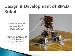
Design & Development of BIPED Robot. Avneesh Agarwal Puneet Singh Vikas Dhiman Under the guidance of Prof. H.O.Gupta EED, IIT Roorkee. Introduction. Objective How we achieved our objective? Walking Algorithms Mathematical Concepts Design of 12 Degree of Freedom Biped

Design & Development of BIPED Robot
E N D
Presentation Transcript
Design & Development of BIPED Robot Avneesh Agarwal Puneet Singh Vikas Dhiman Under the guidance of Prof. H.O.Gupta EED, IIT Roorkee.
Introduction Objective How we achieved our objective? • Walking Algorithms • Mathematical Concepts • Design of 12 Degree of Freedom Biped • Design of 4 Degree of Freedom Biped • Controller Design • Fabrication • Testing and Debugging Why Biped Robots? Applications Objectives Achieved and Future Aspects
Objective of the project • The main objective of this project is to design and construct a biped robot that has the ability to walk forward on a flat plane. • There are three secondary objectives to be achieved in order to achieve the main objective stated above. The three secondary objectives are : • To design and construct the frame and actuators of the robot. The parts needed are to be decided, purchased, fabricated and assembled. • To design the electronic circuit of the robot. The controller circuitry and microcontroller programmer circuit are to be designed. The circuits are to be fabricated and tested for reliability. • To design and program the controller of the robot. A program to implement the walking gait of the robot is to be written and loaded into the microcontroller.
Walking Algorithms • Zero Moment Point (ZMP) locomotion • At every instant there is no moment (torque) in lateral or forward direction i.e. body is in equilibrium. • Can perform complex maneuvers like turning, stair climbing etc. • E.g Honda Asimo (COT=3.2 J.N-1.m-1) • Dynamic Walking • Leg motion is made to imitate inverted pendulum. • Very energy efficient but not able to produce complex maneuvers. • E.g. Cornell Biped(COT=0.2 J.N-1.m-1)
Mathematical Concepts • Coordinate Transformations • DH coordinate system • Direct Kinematics • Inverse Kinematics
DH coordinates - Algorithm Step 1: Locate all joints and assign the joint axes, z0 - zn-1, so that each axis is coincident with the axis of revolution of the corresponding joint. Step 2: Set the origin at a convenient arbitrary point on the z0 (base frame) axis. Chose the x0 and y0 axes so that they form a right-handed co-ordinate frame with z0. For each remaining joint (joints i -> n-1), re-iterate steps 3 - 5. Step 3: If the joint axis, zi, intersects the previous joint axis, zi-1, at a unique point, this point becomes the location for the origin of the joint. In the case of collinear axes, the origin is located at the joint. Step 4: If zi and zi-1 intersect, the x axis, xi, lies in a direction normal to the plane created by the vectors zi and zi-1. For collinear axes, xi lies along the common normal of zi and zi-1. Step 5: yi now forms a right-handed Cartesian co-ordinate frame with xi and zi. Step 6: A co-ordinate frame is assigned for the end-effector (assigned the label joint n). zn is defined along the same axis, with xn and yn forming a convenient Cartesian frame. Step 7: Evaluate the link parametersfor each link: qk = Angle of rotation from xk-1 to xk measured about zk-1. (Joint Angle) Dk = Distance from origin of frame Lk-1 to point bk measured along zk-1. (Joint Distance) Ak = Distance of point bk from the origin of frame Lk measured along xk. (Link Length) ak = rotation of zk-1 to zk measured about xk . (Link Twist Angle)
DH coordinate transformation General Transformation of a coordinate frame w.r.t first frame = 0A1*0A2*…*0An
Design of 12 Degree of Freedom Biped Robot • Mathematical Design • DH Parameter for 12 Motor Biped Robot • Mechanical Design • Mechanical Assemblies • Mechanical Parts • Torque Simulation Results
Mechanical Design For 12 Motor Biped Robot Gait Hip Thigh Leg Ankle Foot
Mechanical Assemblies GAIT Hip Upper Joint HIP Thigh LEG ANKLE FOOT
Mechanical Parts Hitec Servo HSR5498SG
Torque Simulation Results For 12 Motor Biped Robot • 25-29: CHANGE ACTIVE LEG • 30-34: LIFT ACTIVE LEG • 35-39: SWING ACTIVE LEG • 1-4 : LIFT ACTIVE LEG • 5-9: SWING ACTIVE LEG • 10-14: GROUND ACTIVE LEG • 15-24: DOUBLE LIMB SUPPORT PHASE
Design of 4 Degree of Freedom Biped Robot • Mathematical Design • DH Parameter for 4 Motor Biped Robot • Mechanical Design • Mechanical Assemblies • Mechanical Parts • Torque Simulation Results
Torque Simulation Results For 4 Motor Biped Robot Phase I: Lifting Active Leg Phase II: Swinging Active Leg Phase III: Grounding Active Leg Phase IV: Changing Active Leg(Double Limb Support Phase) and Lifting New Active leg Phase V: Swinging New Active leg Phase VI: Grounding Active Leg Phase VII: Double Leg Support Phase
ElectronicDesign • Servo MotorsFutaba S3003: Dimension: 40 x 20 x 37mmWeight: 39.8g Output torque: 3 kg.cm • Microcontroller & circuit elements Microchip PIC18F4550
Execution Circuit Programming & Execution Board
Servo Control Pulse width of 900-1900 microsec + − Pulse width of 20 ms 6 V DC Power Supply
Handling Inputs & Outputs There are basically three types of signal on the port pins. • Digital Outputs • Digital Inputs • Analog Inputs
Digital Inputs/Outputs are through ports A,B,C,D,E Each port has three registers for its operation. These registers are: • TRIS register (Data direction register) (1-Input 0-Output) • PORT register (reads the levels on the pins of the device) • LAT register (Output Latch)
Analog to Digital Conversion ADCON2 ADCON1 ADCON0
Advantages of biped robots • A biped robot would be able to move across uneven discontinuous terrain better than wheeled robots • Biped robot body can be made shorter along the walking direction as compared to multi-legged robots. • Common terrains like staircases are designed for bipedal walking.
Applications • Surveillance along difficult terrain • Outer space exploration • Land mine detection • Nuclear Power plant • Gas leakage detection in coal mines • Can be used in rescue operations • Can replace human worker in long term