living with the lab
living with the lab. Fabrication of a Centrifugal Pump. living with the lab. The content of this presentation is for informational purposes only and is intended only for students attending Louisiana Tech University.

living with the lab
E N D
Presentation Transcript
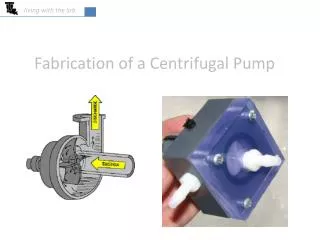
living with the lab Fabrication of a Centrifugal Pump
living with the lab The content of this presentation is for informational purposes only and is intended only for students attending Louisiana Tech University. The author of this information does not make any claims as to the validity or accuracy of the information or methods presented. The procedures demonstrated here are potentially dangerous and could result in injury or damage. Louisiana Tech University and the State of Louisiana, their officers, employees, agents or volunteers, are not liable or responsible for any injuries, illness, damage or losses which may result from your using the materials or ideas, or from your performing the experiments or procedures depicted in this presentation. If you do not agree, then do not view this content. DISCLAIMER
living with the lab Examples of Centrifugal Pumps www.grpumps.com www.oilworksinc.com
living with the lab Examples of Impellers
living with the lab Parts to Fabricate Impeller Fabricated Using a Rapid Prototyping Machine from ABS Plastic Pump Body Fabricated from PVC rod.
living with the lab Raw Materials ½” thick blue-tint PVC sheet $26.29 per square ft PVC = polyvinyl chloride 5/16” bronze rod $6.89 per ft 2” x 2” gray PVC rod $16.23 per ft PVC is made of long chain molecules with a carbon backbone and hydrogen and chlorine side groups Ultra-MachinableHigh-Strength Bearing-Grade Bronze (Alloy 544) Bronze is primarily an alloy of copper and tin. This bronze contains lead, making it easier to machine.
living with the lab Parts and Materials Required for Pump
living with the lab Tools You must become familiar with the operation and safety procedures of the tools before beginning the project.
living with the lab Drill Bits End Mill for sizing Impeller hole for bushing/seal Forstner bits
living with the lab Milling Machine: Prepare Machine for Use Clean and inspect the machine. Inform your instructor if you find any potential damage. To clean, apply a small amount of oil to the x-y table and vise surfaces, and wipe them down with a clean cloth. The oil will keep the unpainted steel surfaces from rusting and will reduce wear on the moving surfaces of the vise. milling vise xy table
living with the lab Milling Machine: Operating the Digital Readout (DRO) Practice moving each of these handles back and forth with the machine turned off until you understand and feel comfortable with machine movements. digital readout (DRO) – used to monitor the x, y and z positions due to turning the 3 crank handles z-direction crank handle for z-translation of entire cutting head assembly z-direction spindle handle for z-translation of spindle only (drill chuck only) (DOES NOT AFFECT DRO READOUT) Make sure lock bolt for x-direction stage is unlocked an turned upward so that it won’t interfere with table movement (or it could break off) y-direction crank handle for x-translation x-direction crank handle for y-translation
living with the lab Milling Machine: Operation of the Digital Readout (DRO) The z-direction readout on the DRO is used to tell you how deep you are drilling. The x- and y-direction readouts can help you accurately position the holes in the faceplate and the pump exit hole. Note that the crank handles for the x, y and z directions cause the DRO values to change, but the spindle handle does not influence DRO readout. To clear the x-reading on the DRO, press <clear> followed by <x>; do likewise for the y and z directions. clear button (the one being pushed)
living with the lab Milling Machine: Safety Features and Operation With the safety shield closed and your safety glasses on, practice turning the machine on and off (turn off with both the off button and the emergency stop). Practice changing the speed of the spindle. emergency stop (hit this button to quickly stop machine) red off button green on button Safety Shield: Do not start machine if this shield is not in place. Be sure that there is adequate clearance between the bottom of this shield and the top of the milling vise before adjusting the crank handle for z-translation of the cutting head assembly. Spindle Speed Control: Use the speeds recommended for each drilling operation
living with the lab Milling Machine: Loading a Workpiece into the Vise and Tool into the Chuck Place the parallels into the vise followed by the workpiece. Then, use the vise handle to tighten the slide on the milling machine. Make sure the workpiece is securely clamped in the vise before beginning work. load drill bit or other tool into chuck and tighten with key nut for locking down x stage of x-y table (be careful not to move the y-stage if this nut is downward (make sure it’s pointing upward), or you could break off the nut. Don’t forget to Remove key from chuck! vise handle
living with the lab Safety Rules • Do not operate any machine unless authorized to do so by the instructor. • Do not attempt to oil, clean, adjust or repair any machine while it is in operation. • Wear appropriate clothing for the work to be done – loose clothing can be caught up in rotating equipment, pulling you into the equipment. • No “horse play” is allowed in the lab. • To prevent tripping or cutting a foot, keep floor clear of scraps, chips and supplies. • Turn off the equipment you are using before leaving it. • Safety glasses or a face shield must be worn when using tools or equipment. • Put tools away when not in use. • Do not use rags on rotating work. • Do not attempt to hold work with rags while using any rotating equipment. • Long hair must be tucked under a cap when you are operating rotating equipment. • Report any unsafe working conditions and/or practices to the instructor. • Take all common sense precautions. If you have an accident, report it immediately to the instructor. Do not begin to fabricate your pump until you have carefully read the operating and safety instructions above and agree to operate the equipment in a responsible manner. You must sign the safety contract before beginning fabrication.
living with the lab The operations below are performed by University technicians (do not do this yourself). Rip the PVC sheet into 2 inch wide strips using a table saw. Then, chop these strips into 2 inch long segments for the pump face plate using a chop saw. Saw the 2 inch x 2 inch PVC rod into a 0.9 inch long segment for the pump body using a chop saw. raw materials table saw chop saw materials after cutting
living with the lab Bushing and Seal: University technicians have fabricated a bushing and seal to prevent your pump from leaking around the DC motor shaft. The seal is made from a bearing grade bronze rod and a small o-ring. The bronze rod is prepared using a lathe, which you will learn to use in ENGR 121. lathe STEP 3: make o-ring seat with 13/64 end mill STEP 2: center drilling with #42 bit STEP 1: bevel bronze rod STEP 4: parting bronze rod STEP 5: glue in o-ring finished bushing / seal
living with the lab Draw an X on the top of the block to find the center
living with the lab Clamp the block into the milling vise – make sure the parallels are supporting the workpiece. parallels
living with the lab Put the N bit into the chuck. Turn the crank handles to move the x-y table until the bit is directly over the “x.” Then tighten down the x- and y-table lock bolts so the table won’t move in the subsequent steps. The lock bolts can get hung up on the x-y table when you are moving it, so check to make sure there isn’t any interference. lock bolt for x-direction
living with the lab Drill N bit hole all the way through block (but not into the vise!!!).You can use either the crank handle or the spindle handle. Note: Set the drilling speed to 40. crank handle for z-translation of entire cutting head assembly spindle handle for z-translation of spindle only (drill chuck only) (DOES NOT AFFECT DRO READOUT)
living with the lab Install the 1 ¼ inch Forstner bit into the chuck. You may need to raise the cutting head to provide room to get the bit into the chuck. After the bit is in and the safety shield is in place, turn the spindle on. Then, lower the cutting head with the z-crank handle until the bit begins to cut the 1 ¼ inch hole. Zero the z-direction on the DRO, and drill down until the depth is about 0.080 inches. Note: Set your drilling speed to 30
living with the lab Install the 1 inch Forstner bit, bring the cutting head down until the bit begins to cut into the block at the bottom of the previous hole. Drill an additional 0.42 inches deeper (for a total depth of ½ inch from the top surface of the block). Note: Set your drilling speed to 30 Expect chips to wrap around the bit during drilling Warning– The drill bit may be very hot. Use a rag or cloth to remove.
living with the lab Unlock the x- and y-stage lock bolts and remove the block from the vise. Flip the pump body over, doing your best to be sure the axis of the hole drilled earlier coincides with the axis of the spindle. To check this, place the N bit back into the chuck, and move the x- and y-stages until the bit is aligned with the hole. Now, remove the N bit and replace it with the ½ inch Forstner bit.
living with the lab Drill a hole 0.11 inches deep using the ½ inch Forstner bit – the DC pump motor will be mounted to this side of the pump body. Note: Set your drilling speed to 40
living with the lab Mark hole for pump outlet as shown below. The exit should roughly be tangent to the 1 inch Forstner hole. drill hole here bit is tangent to 1 inch hole 5/16 inch 11/16 inch
living with the lab Drill the pump exit hole with the Q bit to a depth of 1 inch. Note: Set your drilling speed to 40
living with the lab Mark the locations of the four holes to attach the DC motor to the pump body. 3/16 inch 3/8 inch 1 inch
living with the lab Drill the four holes to attach the DC motor to the pump body using the 5/32 inch bit. Note: Set your drilling speed to 50 The hole being drilled in this picture should be 1/4 inch deep. The hole being drilled in this picture should be 7/16 inch deep.
living with the lab Tap pump exit for a barbed fitting to attach tubing. Place the pump body in the bench vise for tapping. You will need to apply a little bit of axial force to the tap as you get it started in the hole. While you are doing this, keep checking to be sure your tap is perpendicular to the pump body.
living with the lab Press the bronze bushing with the o-ring seal into the pump body until the bushing is flush with the bottom of the 0.11 inch diameter hole. Completely close the jaws of the chuck, and use the z-crank handle to apply the pressing force. We normally don’t use the milling machine as a press, but it’s OK here since pressing forces are small.
living with the lab Make an X on the face place to prepare for drilling. Go ahead and also mark the location of the four screw holes. ¼ inch ¼ inch
living with the lab Using the milling machine, drill the pump inlet hole with a Q bit all the way through face plate as shown. Be sure to support the face plate with the parallels. Note: Set your drilling speed to 40
living with the lab Using the milling machine, drill the four screw holes into the face plate using a #42 drill bit. Note: Set your drilling speed to 50
living with the lab Tap 1/8 inch 27 NPT threads into the face place.
living with the lab Make alignment marks on the pump body and face plate. Clamp the pump body to the pump face plate as shown. Cutting marks into work pieces keeps them from rubbing off. Place the clamped parts in the bench vise as shown, and make alignment marks so you can properly align the face plate to the pump body during later assembly steps. alignment marks
living with the lab Leave the clamped parts in the bench vise. Using the four holes in the face plate as a guide, drill #42 holes deep into pump body (don’t go quite all the way through) using a hand drill (this is not done in the milling machine). Be sure to keep the drill perpendicular to the workpiece to avoid breaking the drill bit. NOTE: The drill is variable speed; practice using the drill without a bit first trying to keep the rotational speed of the drill low for safety. Work toward slow and controlled motion (don’t put your body weight into the drill since suddenly breaking through the workpiece is dangerous). Never use the hand drill unless the workpiece is clamped in the vise.
living with the lab Mount the face plate in the vise. Chase the #42 holes in the face plate with a 5/32 inch bit using a hand drill to provide clearance between the screw and the face plate. d dhole > dscrew dscrew dhole Important: Oversizing these holes allows the screws to easily slide through. The o-ring between the faceplate and body can’t be properly compressed unless these holes have a diameter larger than the screws.
living with the lab Apply Teflon tape to the two barbed fittings, and then screw them into the pump body and into the face plate. Teflon tape helps prevent leaking.
living with the lab Use the two zip ties to attach the DC motor to the pump body. Note: The bronze bushing keeps the axis of the DC motor shaft concentric with the o-ring seal. The seal is attached to the bushing with super glue. If the DC motor shaft doesn’t easily slip into the bushing/seal, then use the #42 drill bit to clean out the bushing hole since excess superglue may have accumulated in the hole during gluing. There is no need to use a drill; you should be able to turn the bit in the hole by hand. Be careful not to remove too much of the o-ring material since this could lead to leakage.
living with the lab Lubricate around the o-ring, being careful not to get lubricant on the motor shaft (since the impeller might slip relative to the pump shaft if the contact interface is lubricated). When using the pump later, be careful not to run the pump dry, since the o-ring seal could get too hot and be damaged, resulting in a leaky pump.
living with the lab Press the impeller onto the shaft of the DC motor, being careful not to break the impeller blades (press straight down with uniform force). The hole in your impeller was sized using a #44 drill bit for a 0.005 inch interference fit between the impeller and the DC motor shaft.
living with the lab Complete the assembly of the pump. keep gap uniform Screw down the four screws until you compress the o-ring enough to prevent leaks. Make sure you have a uniform gap between the pump body and the face plate.
living with the lab Clean up your mess. Make it look better when you leave than it looked when you arrived. Take pride in your lab!!! Step 3: Wipe the machine and the countertop in your area with a rag (an oily rag will keep the milling machine from rusting). Step 1: Brush the larger chips off the machine and vises, collecting them in the dustpan. Dispose of them in the trashcan. Step 2: Vacuum up any remaining small chips (do not vacuum large chips since it will plug up the vacuum cleaner. Step 4: Put all drill bits and the chuck key back into their holder and organize your work area. Inform your instructor is anything is broken, damaged or lost before leaving the classroom.
living with the lab Show the instructor your pump and that your workstation is put back in order.