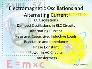
ELECTROMAGNETIC OSCILLATIONS
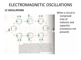
ELECTROMAGNETIC OSCILLATIONS. LC OSCILLATIONS. When a circuit is comprised only of inductor and capacitor (resistance not present).

ELECTROMAGNETIC OSCILLATIONS
E N D
Presentation Transcript
ELECTROMAGNETIC OSCILLATIONS LC OSCILLATIONS When a circuit is comprised only of inductor and capacitor (resistance not present)
Initially the capacitor is fully charged and no current flows in the inductor, as capacitor begins to discharge, current I flows through the inductor which increases to maximum when the capacitor has fully transferred to the magnetic field of the inductor. Energy now flows from the inductor back to the capacitor and when fully charged the capacitor begins to discharge again except that it is in reverse direction.
Energy stored in the electric field of the capacitor at time t is • Energy stored in the magnetic field of inductor at any time • At any time in the circuit the total energy ;
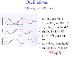
LC Oscillator • Since the circuit has no resistance, energy transferred to thermal energy is zero & U is constant with time But ; (LC oscillation eqn) • Compare this with withsolution
The solution to LC eqn is thus (charge oscillation) • Q is the amplitude of charge oscillation and is the angular frequency. • Differenciating to get i, we have • Differentiating current we have • Sub for q and we have angular frequency.
OSCILLATIONS IN RLC CIRCUIT • When a resistor is added then we have RLC circuit, the total energy no longer remain the same because the resistance convert part of it into thermal energy i.e energy decreases at a rate thus
Dividing through by iand rearranging we have Damped oscillation in an RLC circuit • The solution is • The total energy of the electric field in the capacitor as a function of time is given as • Thus the energy of the electric field oscillates according to a cosine-squared term, and the magnitude of the oscillation decreases exponentially with time.
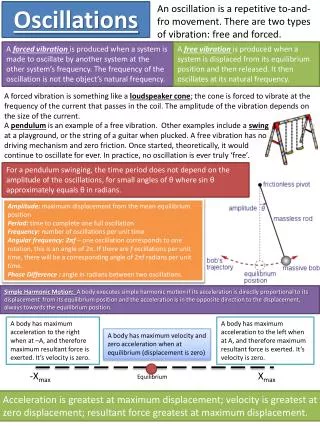
ALTERNATING CURRENT • To make up for damping in the RLC circuit, an external emf device is made to supply an alternating current or simply ac. The oscillating current or emf vary sinusoidally with time, reversing directions. The emf is given as = max (amplitude) is the driving frequency • The current ; is a convention adopted instead of = phase constant since imay not be in phase with . • The driving frequency can be got from
Three simple circuits A resistive load from the loop rule vRalso has an amplitude, VR=εm. Or (Resistor)
A capacitive load • The p.d across the capacitor is Also we have to find the current we differentiate q We then define a quantity called capacitive reactance And also noting that hence, The voltage amplitude Vc and current amplitude Ic are related thus
AN INDUCTIVE LOAD The potential drop across the inductor • Recall that hence p.d across inductor with current changing • Combining we have • To get i, we integrate And replacing -cos(ωdt) with sin(ωdt-90) t for inductor
The series RLC circuit • The alternating emf is now applied to the circuit containing R, L and C which are in series this implies that same current passes through all. (vCand vL) are opposite in direction The denominator is called the impedance Z
The denominator is called the impedance Z thus If we sub for XL and XC ; • If XL > Xc then the circuit is said to be more inductive than capacitive • If XC>XL then the circuit is said to be more capacitive than inductive ( is negative) • If XC=XLthe circuit is said to be in resonance,
RESONANCE • Consider the eqn • I is max when recall that this is same as , the natural frequency of the circuit without external emf. resonance; I is maximum
POWER IN AC CIRCUITS Power P is given as • Average power • The quantity (root mean square current) • Average power also • We can also write And But from the geometry of the system
THE TRANSFORMER • When an ac circuit has only a resistive load, the power factor, cos =1 ; • (I & V are by convention the root mean square values measured by meters at home). • In power transmission, one seeks to transmit at the highest possible voltage & lowest possible current to reduce energy dissipation as a result of the resistance of the conducting wire. • At the same time the end users need low voltage and high current hence the need to be able to raise(for transmission) and lower (for use) the ac voltage in a circuit keeping the power constant. The device for this is called transformer.
The ideal transformer consists of two coils, with different numbers of turns, wound around an iron core. The coils are insulated from the core. The primary winding is connected to an alternating current generator. The relationship between the voltage and current in the two coils and their number of turns is given by - transformaton of voltage If - it is a step up transformer and if it is a step down transformer • But power is constant in both the primary and secondary coils thus, - transformation of current.
Sample problem • Solution In the above figure, R=200 ohms C= 13 microfarad and L=230 miliHenry fd=60 Hz Q-1. if L=0 find a), impedanze Z; b), phase angle and current I
Sample problem/exercise Q-2. in the problem figure; If C=0; find a). Z, b). Phase angle and c). The current I Q-3 in the problem figure; find a). Z, b). Phase angle and c). The current I for the RLC circuit.