Electromagnetic Oscillations in AC Circuits
350 likes | 433 Vues
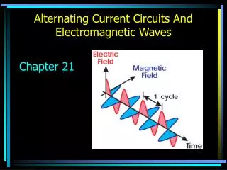
Explore the principles of LC, RLC circuits, and AC circuits, including reactance, impedance, and power factor. Learn about oscillations, energy transfer in circuits, and transformers in alternating current systems. Develop a comprehensive understanding of resonance, power dissipation, and transformer efficiency. Dive deep into practical examples and calculations to enhance your knowledge of electrical circuit analysis.

Electromagnetic Oscillations in AC Circuits
E N D
Presentation Transcript
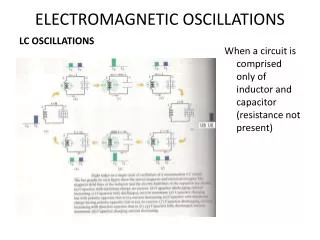
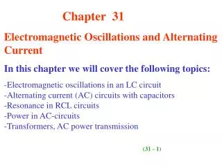
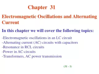
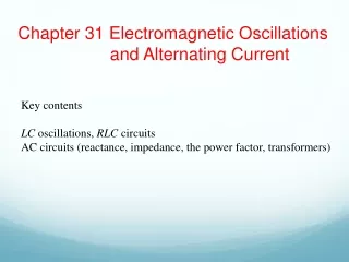
Chapter 31 Electromagnetic Oscillations and Alternating Current Key contents LC oscillations, RLC circuits AC circuits (reactance, impedance, the power factor, transformers)
31.3: The Electrical Mechanical Analogy: The angular frequency of oscillation for an ideal (resistanceless) LC is:
31.4: LC Oscillations, Quantitatively: The Block-Spring Oscillator: The LC Oscillator:
31.4: LC Oscillations, Quantitatively: The electrical energy stored in the LC circuit at time t is, The magnetic energy is: But Therefore
Example, LC oscillator, potential charge, rate of current change
31.5: Damped Oscillations in an RLC Circuit: Analysis: Where And
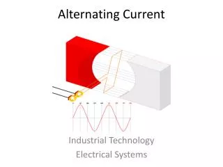
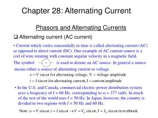
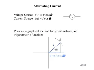
31.6: Alternating Current: wdis called the driving angular frequency, and I is the amplitude of the driven current.
31.7: Three Simple Circuits: i. A Resistive Load: For a purely resistive load the phase constant f = 0°. # We are concerned with the potential drop (voltage) along the current flow, and the phase lag of the current w.r.t. the voltage, which is in phase with the driving AC emf.
31.7: Three Simple Circuits: i. A Resistive Load:
Example, Purely resistive load: potential difference and current
31.7: Three Simple Circuits: ii. A Capacitive Load: XCis called the capacitive reactance of a capacitor. The SI unit of XCis the ohm, just as for resistance R.
31.7: Three Simple Circuits: ii. A Capacitive Load:
Example, Purely capacitive load: potential difference and current
31.7: Three Simple Circuits: iii. An Inductive Load: The XLis calledthe inductive reactanceof an inductor. The SI unit of XLis the ohm.
31.7: Three Simple Circuits: iii. An Inductive Load:
Example, Purely inductive load: potential difference and current
31.9: The Series RLC Circuit: Fig. 31-14 (a) A phasor representing the alternating current in the driven RLC circuitat time t. The amplitude I, the instantaneous value i, and the phase(wdt-f) are shown. (b) Phasors representing the voltagesacross the inductor, resistor, and capacitor, oriented with respect to the current phasor in (a). (c) A phasor representing thealternating emf that drives the current of (a). (d) The emf phasor is equal to the vector sum of the three voltage phasors of (b).Here, voltage phasors VLand VChave been added vectorially to yield their net phasor (VL-VC).
31.9: The Series RLC Circuit, Resonance: For a given resistance R, that amplitude is a maximum when the quantity (wdL -1/wdC) in the denominator is zero. The maximum value of I occurs when the driving angular frequency matches the natural angular frequency—that is, at resonance.
31.10: Power in Alternating Current Circuits: The instantaneous rate at which energy is dissipated in the resistor: The average rate at which energy is dissipated in the resistor, is the average of this over time: Since the root mean square of the current is given by: Similarly, With Therefore, where The factor cos ϕ is called the power factor. For a given emf and a desired power consumption, a lower power factor means a larger current, which will cause larger line loss.
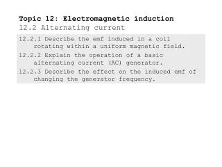
31.11: Transformers: In electrical power distribution systems it is desirable for reasons of safety and for efficient equipment design to deal with relatively low voltages at both the generating end (the electrical power plant) and the receiving end (the home or factory). On the other hand, in the transmission of electrical energy from the generating plant to the consumer, we want the lowest practical current (hence the largest practical voltage, for a given generation power) to minimize I2R losses (often called ohmic losses) in the transmission line. For a given emf source, the maximum energy transfer to a resistive load is to have the load resistance equal to the emf source resistance. It is the same for AC devices, but here we need impedance matching. A transformer can effectively change the voltage and the impedance in a circuit.
31.11: Transformers: Because B varies, it induces an emf in each turn of the secondary. This emf per turn is the same in the primary and the secondary. Across the primary, the voltage Vp=EturnNp. Similarly, across the secondary the voltage is Vs =EturnNs.
31.11: Transformers: If no energy is lost along the way, conservation of energy requires that Here Reqis the value of the load resistance as “seen” by the generator. For maximum transfer of energy from an emf device to a resistive load, the resistance of the load must equal the resistance of the emf device. For ac circuits, for the same to be true, the impedance (rather than just the resistance) of the load must equal that of the generator.
Homework: Problems 17, 26, 42, 48, 58