Download
1 / 26
260 likes | 562 Vues
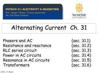
Alternating Current Ch. 31. Phasors and AC (sec. 31.1) Resistance and reactance (sec. 31.2) RLC series circuit (sec. 31.3) Power in AC circuits (sec. 31.4) Resonance in AC circuits (sec. 31.5) Transformers (sec. 31.6). C 2012 J. F. Becker.

E N D
Alternating Current Ch. 31 Phasors and AC (sec. 31.1) Resistance and reactance (sec. 31.2) RLC series circuit (sec. 31.3) Power in AC circuits (sec. 31.4) Resonance in AC circuits (sec. 31.5)Transformers (sec. 31.6) C 2012 J. F. Becker
Learning Goals - we will learn: ch 31 • How phasors make it easy to describe sinusoidally varying quantities.• How to analyze RLC series circuits driven by a sinusoidal emf.• What determines the amount of power flowing into or out of an AC circuit. • How an RLC circuit responds to emfs of different frequencies.
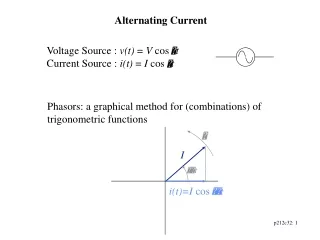
Phasor diagram -- projection of rotating vector (phasor) onto the horizontal axis represents the instantaneous current.
Notation:-lower case letters are time dependent and -upper case letters are constant. For example, i(t) is the time dependent current andI is current amplitude; VR is the voltage amplitude (= IR ). Graphs (and phasors) of instantaneous voltage and current for a resistor. i(t) = I cos wt (source) vR(t) = i(t) R vR(t) = IR cos wtwhere VR = IR is the voltage amplitude. VR = IR
Graphs of instantaneous voltages for RLC series circuit. (The phasor diagram is much simpler.)
i(t) = I cos wt (source) vL(t) = L di / dt vL(t) = L d(I cos wt )/dt vL(t) = -IwL sin wtvL(t) = +IwL cos (wt + 900)where VL = IwL (= IXL)is the voltage amplitude and f = +900 is the PHASE ANGLE(angle between voltage across and current through the inductor).XL = wL Graphs (and phasors) of instantaneous voltage and current for an inductor. E L I VL L I
Graphs (and phasors) of instantaneous voltage and current showing phase relation between current (red) and voltage (blue).Remember: “ELI the ICE man”
Crossover network in a speaker system.Capacitive reactance: XC =1/wCInductive reactance: XL = wL
Phasor diagrams for series RLC circuit (b) XL > XC and (c) XL < XC.
Graphs of instantaneous voltages for RLC series circuit. (The phasor diagram is much simpler.)
Graphs of instantaneous voltage, current, and power for an R, L, C, and an RLC circuit. Average power for an arbitrary AC circuit is 0.5 VI cosf = V rms I rms cos f.
Instantaneous current and voltage: The average power is half the product of I and the component of V in phase with it. Average power depends on current and voltage amplitudes AND the phase angle f:
Graph of current amplitude I vs source frequency wfor a series RLC circuitwith various values of circuit resistance. The resonance frequency is at w = 1000 rad / sec(where the current is at its maximum)
AMPLITUDE MODULATION (AM) of CARRIER WAVEresonance frequency (fo) Electric field amplitude AM modulatedElectric field amplitude
FREQUENCY MODULATION (AM) of CARRIER WAVEresonance frequency (fo) Electric field amplitude FM modulatedElectric field amplitude
A radio tuning circuit at resonance. The circles denote rms current and voltages.
e= - dF B / dt TRANSFORMERS can step-up AC voltages or step-down AC voltages. Transformer: AC source is V1 and secondary provides a voltage V2 to a device with resistance R. e2 /e1 = N2/N1 V1I1 = V2I1 FB=FB
(a) Primary P and secondary S windings in a transformer. (b) Eddy currents in the iron core shown in the cross- section AA. (c) Using a laminated core reduces the eddy currents.
Large step-down transformers at power stations are immersed in tanks of oil for insulation and cooling.
A mathematical model of Earth's magnetic field near the core. (Courtesy: Gary Glatzmaier)
Review See www.physics.sjsu.edu/becker/physics51 C 2012 J. F. Becker
PREPARATION FOR FINAL EXAM At a minimum the following should be reviewed:Gauss's Law - calculation of the magnitude of the electric field caused by continuous distributions of charge starting with Gauss's Law and completing all the steps including evaluation of the integrals.Ampere's Law - calculation of the magnitude of the magnetic field caused by electric currents using Ampere's Law (all steps including evaluation of the integrals).Faraday's Law and Lenz's Law - calculation of induced voltage and current, including the direction of the induced current. Calculation of integrals to obtain values of electric field, electric potential, and magnetic field caused by continuous distributions of electric charge and current configurations (includes the Law of Biot and Savart for magnetic fields).Maxwell's equations - Maxwell's contribution and significance.DC circuits - Ohm's Law, Kirchhoff's Rules, series-parallel combinations, power. Series RLC circuits - phasors, phase angle, current, power factor, average power. Vectors - as used throughout the entire course.