Electromagnetic Oscillations and Alternating Current
Electromagnetic Oscillations and Alternating Current. LC Oscillations Damped Oscillations in RLC Circuits Alternating Current Resistive, Capacitive, Inductive Loads Reactance and Impedance Phase Constant Power in AC Circuits Transformers. pps by C Gliniewicz.

Electromagnetic Oscillations and Alternating Current
E N D
Presentation Transcript
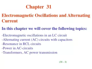
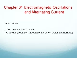
Electromagnetic Oscillations and Alternating Current LC Oscillations Damped Oscillations in RLC Circuits Alternating Current Resistive, Capacitive, Inductive Loads Reactance and Impedance Phase Constant Power in AC Circuits Transformers pps by C Gliniewicz
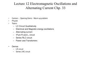
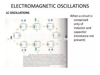
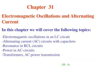
In circuits containing a resistor and a capacitor, the charge, current and potential difference increase or decrease exponentially. The same occurs in a circuit containing and inductor and a resistor. Both occur on a time scale based on the time constant, . In a circuit containing an inductor an a capacitor, the charge, current and potential difference do not decay exponentially, but vary sinusoidally. These are called electromagnetic oscillations. Energy can be stored in the capacitor or the inductor. The total amount of energy stored is constant. When all the energy is stored in the capacitor, obviously the energy in the inductor will be zero and visa versa. This will continue forever if there is no resistance to drain away energy. Since there is always some resistance present, these oscillations will eventually die away and dissipate as heat. One can imagine an analogy with the mechanical energy in a spring-mass system. Friction will eventually cause all the energy to disappear as heat. We can compare the angular frequency, , in each system. pps by C Gliniewicz
We can compare the differential equations for each type of system. It is from these equations that one can determine the angular frequency of the LC circuit which was given previously. The electrical and magnetic energies in an LC circuit also vary with the sine and cosine functions. The maximum value of both the magnetic and electrical energies is At any time the total energy is equal to When the electrical energy is the maximum, the magnetic energy is zero and visa versa. pps by C Gliniewicz
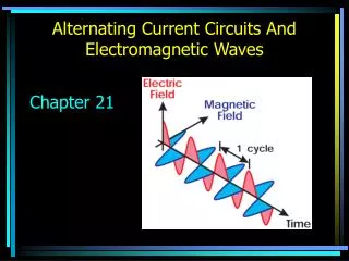
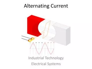
When a resistor is added to the LC circuit, an RLC circuit is created. The resistor is constantly draining energy as heat and one has a damped oscillation. This can be shown by writing an equation for the rate at which energy is dissipated. The oscillations in an RLC circuit will not damp out if an external emf device supplies enough energy to make up for the thermal energy that is dissipated in the resistor. This becomes an alternating current source. In North America the oscillations have a frequency of 60 hertz, reversing the current’s direction 120 times per second. Although the electrons have a very small drift velocity and the alternating current negates that motion, the electric field moves at very high speed. One can write an equation for the emf. pps by C Gliniewicz
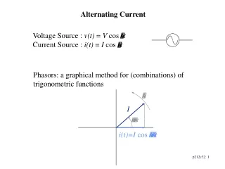
The driving angular frequency is d and the driving frequency is fd. The free oscillations vary with the inductance and capacitance. This is the natural angular frequency. Resonance occurs in the circuit when the natural angular frequency is equal to the driving frequency. In a circuit containing only a resistor, the current and the emf are in phase with one another as both vary with the sine. These can be represented by vectors called phasors. These phasors rotate about the origin with the driving angular frequency. The length of the phasors vary with the magnitude of the voltage and current. The rotation angle of each phasor in this case is the same. In a circuit with a capacitor can act as a resistive load. In this case, the resistance is called the capacitive reactance. pps by C Gliniewicz
The current in a capacitive circuit leads the voltage by 90 degrees or π/2 radians. In an inductive circuit, there is an inductive reactance similar to the capacitive reactance. In an inductive circuit, the current lags the voltage by 90 degrees or π/2 radians. In a resistive circuit, the current and voltage are in phase so the phasor for each has the same angle. In a capacitive circuit, the current leads the voltage by π/2 radians and the angle of the voltage is π/2 radians less than that of the current. In an inductive circuit, the current lags the voltage by π/2 radians, and the angle of the voltage phasor is π/2 radians greater than that of the current. pps by C Gliniewicz
Impedance, Z, is the equivalent of resistance. Reactance has the units of resistance. The phase angle, Ф, can be defined by the reactances and the resistance in the circuit. Power in an AC circuit varies with the square of the sine. The cosine function is called the power factor. pps by C Gliniewicz
A transformer is an iron core with wire from one circuit, coiled on one side of the iron core and wire from a second circuit coiled on the other side of the core. The iron core provides a path for the magnetic field. The changing magnetic field in the primary coil produces a changing magnetic in the iron core. The changing magnetic field sets up a current in the secondary wire. The number of coils in the primary and secondary coils determines the change in potential and current in the secondary coil. The number of coils in the primary and secondary are designated by N. pps by C Gliniewicz