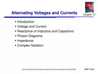
Alternating Current and Voltages
Alternating Current and Voltages. Sinusoidal Waves. Objective of Lecture. Discuss the characteristics of a sinusoidal wave. Define the mathematical relationship between the period, frequency, and angular frequency of a sine wave. Explain how to define the amplitude of a sine wave.

Alternating Current and Voltages
E N D
Presentation Transcript
Alternating Current and Voltages Sinusoidal Waves
Objective of Lecture • Discuss the characteristics of a sinusoidal wave. • Define the mathematical relationship between the period, frequency, and angular frequency of a sine wave. • Explain how to define the amplitude of a sine wave. • Describe what a phase angle is and the difference between lagging and leading signals.
Characteristics of a Sine Wave • The length of time it takes to complete one cycle or conversely the number of cycles that occur in one second. • Period • Frequency • Angular Frequency • The maximum and minimum voltage or current swing • Amplitude • Peak-to-peak amplitude • Value of the root mean square (RMS) • Average value of a sine wave • DC offset • Comparison between two sine waves • Phase angle • Lagging and leading signals
Period, T The time that it takes for a sine wave to complete one full cycle. This can be measured by finding the times at which the signal crosses zero (need two zero crossings). The unit usually used is seconds (s). An alternative way to measure the period is to determine the time required for the sine wave return to the same maximum or minimum value. t1 t2
Frequency, f • The number of cycles a sine wave will complete in one second(fractions are okay). The unit is cycles/second or Hertz (Hz). • The longer the period, the lower the frequency is. • The shorter the period, the higher the frequency is.
Electric Utilities • Standardization on the frequency of the electricity distribution systems didn’t occur until the mid-1900’s. • The frequency of the ac voltage supplied by power companies in the US is 60 Hz. • The frequency used in much of Europe and Asia is 50 Hz. • While some electronic circuits function properly when connected to a power supply operating at either frequency, some are designed for a specific frequency, which is one reason why power adaptors are needed when you travel. • If you look at the label on the tablet ‘brick’, the frequency of the ac signal is specified.
Angular frequency • Motors are used in the alternators in coal- and gas-powered electric generation stations. One full rotation of the motor shaft produces one complete cycle of the ac electricity produced. • Position of the motor shaft is measured in radians (rad) or degrees (o). • 1 rad = 57.3o • 2p rad = 360o
Amplitude Peak amplitude Peak-to-Peak amplitude
Instantaneous Value • Instantaneous value or amplitude is the magnitude of the sinusoid at a point in time.
Average Value • The average value of a sinusoid signal is the integral of the sine wave over one full cycle. This is always equal to zero. • If the average of an ac signal is not zero, then there is a dc component known as a DC offset.
Root Mean Square (RMS) • Most equipment that measure the amplitude of a sinusoidal signal displays the results as a root mean square value. This is signified by the unit Vac or VRMS. • RMS voltage and current are used to calculate the average power associated with the voltage or current signal in one cycle.
Phase Angle • The phase angle is an angular measurement of the position of one sinusoid signal with respect to a reference. • The signal and reference must have the same frequency.
Calculation of Phase • Suppose there are three signals • One signal is the reference • I have chosen the reference to be the signal in blue on the following slide • The phase of the other two signals will be calculated with respect to the reference signal. • The period of each signal should be the same, which means that all signals have the same frequency.
Voltage (V) Time (seconds)
Example #1 • Calculate the period, T, for the reference signal • This is the time for a full cycle to be completed. • T= 500 second for Signal 1 • Calculate the difference in time between zero crossings of • Signal 2 and Signal 1: Dt = 40 second – 0 seconds = 40 s • Signal 3 and Signal 1: Dt = 480 seconds – 0 seconds= 480 s
Example #1 (con’t) • The sinusoidal function that describes Signal 1, the reference voltage, is V(t) = 5V sin (wt) where w = 2p/T = 12.6 mrad/s • To write the sinusoidal function that describes Signals 2 and 3, we need to address the fact that there is a shift in the zero crossings V(t) = A sin (wt + f) where w = 2p/T f = -2p Dt/T in radians or f = -360o Dt/T • f is called the phase shift
Lagging and Leading • Don’t get fooled by the positions of the curves on the graph! • Signal 2: V(t) = 5V sin [(12.6 mrad/s)t – 28.8o] • f is -0.502 radians or -28.8 degrees • Signal 2 lags Signal 1 as it reaches zero at a later time than Signal 1 • Signal 3: V(t) = 5V sin [(12.6 mrad/s)t + 14.4o] • f is 0.251 radians or 14.4 degrees • Signal 3 leads Signal 1 as it reaches zero at an earlier time than Signal 1
Writing Formulas where f is in degrees and the units for w are usually not included.
Summary • AC signals are sinusoidal functions. • The mathematical description of the sinusoid includes the peak amplitude and the angular frequency and may include a phase angle. • RMS values of a sinusoid are calculated using the formula • Phase angle for a sinusoid is calculated with respect to a reference. • A signal lags a reference when fsignal – freference < 0o. • It leads a reference when fsignal – freference > 0o.