Download
1 / 30
300 likes | 729 Vues
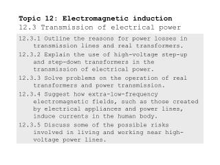
Topic 12: Electromagnetic induction 12.2 Alternating current. 12.2.1 Describe the emf induced in a coil rotating within a uniform magnetic field. 12.2.2 Explain the operation of a basic alternating current (AC) generator.

E N D
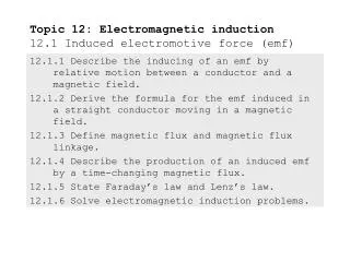
Topic 12: Electromagnetic induction12.2 Alternating current 12.2.1 Describe the emf induced in a coil rotating within a uniform magnetic field. 12.2.2 Explain the operation of a basic alternating current (AC) generator. 12.2.3 Describe the effect on the induced emf of changing the generator frequency.
= -N∆/∆t Faraday’s law Topic 12: Electromagnetic induction12.2 Alternating current Describe the emf induced in a coil rotating within a uniform magnetic field. Recall Faraday’s law: From the formula we see that there are three ways to increase the induced emf of a rotating coil: (1) Increase the number of turns N in coil. (2) Increase the flux change ∆. (3) Decrease the time ∆tover which the flux changes. FYI Recall that = BAcos.Given the uniform magnetic field and rotating coil, B and A are constant. Thus the flux change ∆ will be due only to the change in the angle ∆.
Topic 12: Electromagnetic induction12.2 Alternating current Describe the effect on the induced emf of changing the generator frequency. PRACTICE: What is the effect of increasing the frequency of the generator on the induced emf? SOLUITON: From the previous slide (Point 3) we noted that if we decrease∆t then we will increase the induced emf. But if we decrease ∆t then we decrease T the period of rotation (time for each revolution). Recalling that frequency f = 1/T, we see that as T decreases, f increases. Thus increasing the frequency of a generator increases the induced emf.
BA / Tm2 t/s -BA Topic 12: Electromagnetic induction12.2 Alternating current Describe the emf induced in a coil rotating within a uniform magnetic field. Consider the rectangular loop of wire made to rotate in the fixed magnetic field shown: At this instant = BAcos0º = +BA. A bit later has changed: = BAcos45º = +0.7BA. When = 90º: = BAcos90º = 0. As continues to increase, the flux becomes negative. A sinusoidal pattern emerges. B B A B A A
BA 0 / Tm2 / V t/s t/s = NBAsin t induced emf (rotating coil, N loops, constant B-field) ( = angular frequency) -BA -0 Topic 12: Electromagnetic induction12.2 Alternating current Describe the emf induced in a coil rotating within a uniform magnetic field. Since = -∆/∆twe see that the induced emf is the inverse slope of the flux. Since the slope of the cosine plot is proportional to the sine graph we see that BAsin. In Topic 4 we learned that the constant of proportionality is the angular frequency (measured in radians per second). Thus for a coil of N loops rotating in a constant magnetic field we have an induced emf given by:
= NBAsint induced emf (rotating coil, N loops, constant B-field) ( = angular frequency) Topic 12: Electromagnetic induction12.2 Alternating current Describe the emf induced in a coil rotating within a uniform magnetic field. EXAMPLE: A coil of wire having dimensions 2.5 cm by 3.2 cm has 250 turns. It is rotating at a frequency of 60 Hz in a constant magnetic field having a strength of 1.5 T. (a) What is its peak voltage 0? (b) What is the time dependence of its emf? SOLUTION: Recall that = 2f = 2(60) = 120. (a) A = (0.025)(0.032) = 0.00080 m2. Then 0 = NBA = 250(1.5)(0.00080)120 = 110 V. (b) = NBAsint = 110sin(120t).
= NBAsint induced emf (rotating coil, N loops, constant B-field) = 2fNBAsin2ft = 0 sin2ft ( Where 0 =2fNBA ) Topic 12: Electromagnetic induction12.2 Alternating current Describe the effect on the induced emf of changing the generator frequency. EXAMPLE: Rewrite the generator induced emf formula in terms of frequency f, rather than angular frequency . SOLUTION: Since = 2f we have = NBAsint = 2fNBAsin2ft = 0 sin2ft FYI 0 =2fNBA clearly shows that increasing the frequency increases the induced emf of the coil.
Output voltage N S Topic 12: Electromagnetic induction12.2 Alternating current Describe the emf induced in a coil rotating within a uniform magnetic field. EXAMPLE: Here is a simplified one-loop generator: Some mechanical means makes the coil rotate (say a steam turbine or paddle wheels). The alternating current is picked up by brushes riding on two conducting rings that each touch only one end of the coil, as shown. FYI The schematic representation of an AC voltage supply or generator is .
Topic 12: Electromagnetic induction12.2 Alternating current 12.2.4 Discuss what is meant by the root mean squared (rms) value of an alternating current or voltage. 12.2.5 State the relation between peak and rms values for sinusoidal currents and voltages. 12.2.6 Solve problems using peak and rms values. 12.2.7 Solve AC circuit problems for ohmic resistors.
170 t/s / V -170 (+) (+) (-) (-) Topic 12: Electromagnetic induction12.2 Alternating current Discuss what is meant by the root mean squared (rms) value of an alternating current or voltage. The voltage produced by American power plants is marketed as 120 V AC, but if you were to record the voltage over time you would discover that it varies between -170 V and +170 V. The value that is marketed is essentially sort of an “average” voltage value. The problem with finding the usual average of a sinusoidal function is that it is zero! (+)and(-) areas cancel. 170 t/s / V -170
0 t/s / V -0 02 2 Topic 12: Electromagnetic induction12.2 Alternating current Discuss what is meant by the root mean squared (rms) value of an alternating current or voltage. The way to find the average of a regularly alternating voltage is called the root mean squared. What we do is find the area under the squared value of the sinusoidal voltage so that no cancellation occurs! Consider the dashed line located at 02/2: Visualize the lobes above the dashed line filling in the troughs below. 02 0 t/s
V V0 t -V0 V2 V02 0 t Topic 12: Electromagnetic induction12.2 Alternating current Discuss what is meant by the root mean squared (rms) value of an alternating current or voltage. The AC rms values are equivalent to the constant DC values that would dissipate the same power. EXAMPLE: Find the rms voltage for the “triangular” wave shown here: SOLUTION: Note that there are equal (+) and (-) areas and the straight-forward average is zero. Thus use the rms: Map out a single period T: Find the area under the squared [A = (1/2)bh]: A = 2(1/2)(T/4)(V02) + (1/2)(T/2)(V02) = (1/2)TV02. The mean height is thus A/T = (1/2)V02 = V02/2. Thus Vrms = V0/ 2. T T T 4 T 4 T 2
Vrms = V0/ 2 Irms = I0/ 2 root mean squared (rms) of an alternating voltage root mean squared (rms) of an alternating current (Where V0 is the peak voltage.) (Where I0 is the peak current.) Topic 12: Electromagnetic induction12.2 Alternating current State the relation between peak and rms values for sinusoidal currents and voltages. We then define the root mean squared value of an alternating voltage Vrms as A current that is set up by an alternating voltage will likewise be alternating. Similarly, we define the root mean squared value of an alternating current Irmsas FYI Think of rms values as “DC equivalents.”
Topic 12: Electromagnetic induction12.2 Alternating current Solve problems using peak and rms values. PRACTICE: “Mains” (outlet) electricity in the UK is rated at 220 V. This is an rms value. Find the peak voltage from a UK outlet. SOLUTION: Vrms= V0/ 2 Thus V0 = 2Vrms =2(220) = 310 V. FYI Travelers bring voltage converters along for their personal appliances.
electrical power (DC) electrical power (AC) P = VI = I2R = V2/R P = VrmsIrms = Irms2R = Vrms2/R Topic 12: Electromagnetic induction12.2 Alternating current Solve problems using peak and rms values. It is hoped that you recall the power formulas for DC (shown here): The whole reason for using the rms values for AC current and voltage is this: -Power consumption doesn’t depend on the peak voltage (and peak current); rather, it depends on the rms values, since they are an average. PRACTICE: Show that for an AC circuit P = (1/2)V0I0. SOLUTION: P = VrmsIrms = (V0/ 2)(I0/ 2) = (1/2)V0I0.
Topic 12: Electromagnetic induction12.2 Alternating current Solve problems using peak and rms values. Power consumption is given by P = VrmsIrms which we just showed to be (1/2)V0I0.
Topic 12: Electromagnetic induction12.2 Alternating current Solve problems using peak and rms values. This is a straight-forward definition of rms current.
I02 I02 T 2 T 2 Topic 12: Electromagnetic induction12.2 Alternating current Solve problems using peak and rms values. First we square the values over one period T: We then find the squared area: I02T/2 + I02T/2 = I02T. Then we find the mean height: A/T = I02T/T = I02. Then we take the square root: I = I0.
= NBAsint induced emf (rotating coil, N loops, constant B-field) = 2fNBAsin2ft = 0 sin2ft ( Where 0 =2fNBA ) Topic 12: Electromagnetic induction12.2 Alternating current Solve problems using peak and rms values. Note from the second formula that if f’ = 2f, then V’ = 2V where V and V’ are peak values. Then Vrms = V’/ 2 = 2V/ 2 = 2V.
ac circuits and ohmic resistors Vrms = IrmsR (V0 = I0R) Topic 12: Electromagnetic induction12.2 Alternating current Solve AC circuit problems for ohmic resistors. If a resistor is connected to an AC supply, the following relationship holds: This relationship shows that I and V are proportional to each other and in phase. This may seem an obvious relationship but in AC circuits there are com- ponents called capacitors and inductors which change the phase relationship between I and V. Consumes energy Stores B-field Stores FYI IB does NOT require you to know about these or impedance (a resistive component of capacitors and inductors. E-field
Topic 12: Electromagnetic induction12.2 Alternating current Solve AC circuit problems for ohmic resistors. Power dissipation depends of rms values – that is why we use them after all. Thus P = Irms2R = I02R/2 (since Irms = I0/ 2). If I0’ = 2I0 then P’ = I0’2R/2 P’ = (2I0)2R/2 P’ = 4I02R/2 P’ = 2I02R.
electrical power (AC) P = VrmsIrms = Irms2R = Vrms2/R Topic 12: Electromagnetic induction12.2 Alternating current Solve AC circuit problems for ohmic resistors. Since Vrms=V0/ 2 then P = Vrms2/2R = (V0/ 2)2/R = V02/2R.
Topic 12: Electromagnetic induction12.2 Alternating current Solve AC circuit problems for ohmic resistors. EXAMPLE: A 60-Hz generator which produces an induced emf having a maximum value of 0 = 140 V is connected to a resistor of 28 as shown. Find the equation of the current I as a function of time. SOLUTION:Use V = V0 sin2ft and V0 = I0R. Since V0 = I0R we have V0 = I0R 140 = I0(28) I0 = 5.0 Then I = I0sin2ft = 5.0sin260t = 5.0sin120t.
Topic 12: Electromagnetic induction12.2 Alternating current 12.2.8 Describe the operation of ideal transformers. 12.2.9 Solve problems on the operation of ideal transformers.
Topic 12: Electromagnetic induction12.2 Alternating current Describe the operation of ideal transformers. A transformer is a device that changes the voltage from, say, 120 VAC to 60 VAC (called a step down transformer) or from, say, 120 VAC to 240 VAC (called a step up transformer). Here is how it works: One coil, called the primary winding, is wrapped around a soft iron core as shown: Then another coil, called the secondary winding, is wrapped around the same soft iron core, but with a different number of loops. Primary Secondary Step Down Transformer Secondary Primary Step Up Transformer FYI You determine type by observing the loop ratio.
Is/Ip= Vp/Vs = Np/Ns the ideal transformer Topic 12: Electromagnetic induction12.2 Alternating current Describe the operation of ideal transformers. In an ideal transformer there is no power loss in going from the primary side to the secondary side. Thus IpVp = IsVs Is/Ip= Vp/Vs. We also know that for each winding the voltage is proportional to the number N of loops. Therefore Vp Np and Vs Ns and we see that Vp/Vs = Np/Ns. Putting it all together we get the following: FYI The schematic representation of an ideal transformer is shown here:
Topic 12: Electromagnetic induction12.2 Alternating current Describe the operation of ideal transformers. EXAMPLE: The iron core of a transformer is often laminated (layered and insulated from other layers) to reduce the eddy current energy losses. The primary and secondary coils are often concentric: COIL 1 COIL 2
Topic 12: Electromagnetic induction12.2 Alternating current Solve problems on the operation of ideal transformers. For an ideal transformer there is no power loss between primary and secondary coils. Thus VpIp = VsIs.
Topic 12: Electromagnetic induction12.2 Alternating current Solve problems on the operation of ideal transformers. Since V N, Vs = 2Vp. Frequency is not changed in a transformer.