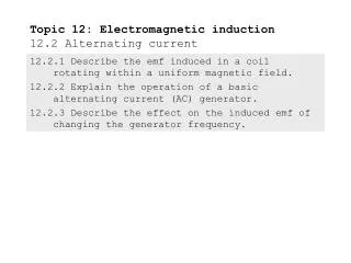
12.2 Alternating current
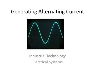
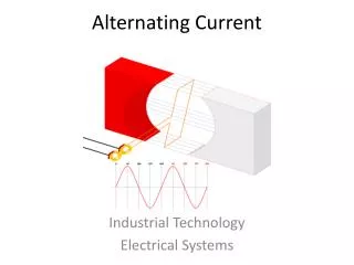
12.2 Alternating current. 2 hours. Alternating Current. The induced emf in a coil rotated within a uniform magnetic field is sinusoidal if the rotation is at constant speed.

12.2 Alternating current
E N D
Presentation Transcript
12.2 Alternating current 2 hours
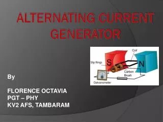
Alternating Current • The induced emf in a coil rotated within a uniform magnetic field is sinusoidal if the rotation is at constant speed. • The most important practical application of the Laws of Electromagnetic Induction was the development of the electric generator or dynamo.
Link to Java Applet • http://www.walter-fendt.de/ph14e/generator_e.htm
Changing the Frequency of the Generator • The emf of a rotating coil can be calculated at a given time. If a coil of N turns has an area A, and its normal makes an angle θ with the magnetic field B, then the flux-linkageFis given by: • Using calculus and differentiating cosθ, the relationship for e.m.f. becomes:
Remember from your knowledge of rotational motion that Δ θ ÷ Δt = the angular velocity, w, in rad s-1 = 2 π f • Also θ = ωt = 2πft • so that ε = ω ×N×A×B ×sin(ωt) or ε = 2πf ×N×A×B × sin(2 π f t) • When the plane of the coil is parallel to the magnetic field, sin ωt will have its maximum value as ωt = 90°, so sin ωt = 1. This maximum value for the emf ε0 is called the peak voltage, and is given by: ε0 = ω NBA • Therefore: ε = ε0 sin(ω t) • The frequency of rotation in North America is 60 Hz but the main frequency used by many other countries is 50 Hz. Note that if the speed of the coil is doubled then the frequency and the magnitude of the emf will both increase.
Root Mean Square (rms) Quantities • An alternating current varies sinusoidally and can be represented by the equation I = I0sin(ωt) • where I0is the maximum current called the peak current as shown in Figure 1223 for a 50 Hz mains supply. • In commercial practice, alternating currents are expressed in terms of their root-mean-square (r.m.s.) value.
The r.m.s. value of the alternating current that produces the power is equal to the d.c. value of the direct current. • For the maximum value in a.c., the power dissipated is given by P = V0 sin(ωt) × I0 sin(ωt) = V0I0 sin2(ωt) • This means that the power supplied to the resistor in time by an alternating current is equal to the average value of I 2R multiplied by time. P = I 2ave × R = I02R sin2ωt • Because the current is squared the, the value for the power dissipated is always positive.
The value of sin2ωt will therefore vary between 0 and 1. Therefore its average value = (0 + 1) / 2 = 1/2 • Therefore the average power that dissipates in the resistor equals: or • So the current dissipated in a resistor in an a.c. circuit that varies between I0 and -I0 would be equal to a current I0 /√2 dissipated in a d.c circuit. This d.c current is known as r.m.s. equivalent current to the alternating current.
RMS Current and Voltage • It can be shown that: • Provided a circuit with alternating current only contains resistance components, it can be treated like a direct current circuit.
The Transformer • A useful device that makes use of electromagnetic induction is the ac transformer as it can be used forincreasing or decreasing ac voltages and currents.
The Transformer • It consists of two coils of wire known as the primary and secondary coils. Each coil has a laminated (thin sheets fastened together) soft iron core to reduce eddy currents (currents that reduce the efficiency of transformers). The coils are then enclosed with top and bottom soft iron bars that increase the strength of the magnetic field. • A typical circuit for a simple transformer together with the recommended circuit symbol.
Transformers • When an ac voltage is applied to the primary coil, an ac voltage of the same frequency is induced in the secondary coil. This frequency in North America is 60 Hz. • When a current flows in the primary coil, a magnetic field is produced around the coil. It grows quickly and cuts the secondary coil to induce a current and thus to induce a magnetic field also. When the current falls in the primary coil due to the alternating current, the magnetic field collapses in the primary coil and cuts the secondary coil producing an induced current in the opposite direction.
Transformers • The size of the voltage input/output depends on the number of turns on each coil. It is found that • Where N = the number of turns on a designated coil and I is the current in each coil.
It can be seen that if Ns is greater than Np then the transformer is a step-up transformer. If the reverse occurs and Ns is less than Np it will be a step-down transformer. • If a transformer was 100% efficient, the power produced in the secondary coil should equal to the power input of the primary coil. In practice the efficiency is closer to 98% because of eddy currents. • This means that if the voltage is stepped-up by a certain ratio, the current in the secondary coil is stepped-down by the same ratio.
Transformer Java Applet • http://micro.magnet.fsu.edu/electromag/java/transformer/