Download

1 / 32
330 likes | 1k Vues
Prepared By :. SHUNT CAPACITOR FUNDAMENTALS AND PROTECTION. OVERVIEW. (1) Introduction (2) Configurations (3) Design (4) Operation (5) Protection (6) Conclusions. INTRODUCTION.

E N D
Prepared By : SHUNT CAPACITOR FUNDAMENTALS AND PROTECTION
OVERVIEW (1) Introduction (2) Configurations (3) Design (4) Operation (5) Protection (6) Conclusions
INTRODUCTION • Shunt capacitor banks (SCB) are mainly installed to provide capacitive reactive compensation/power factor correction. • They are installed near the load terminals, in factory substations, in the receiving substations to provide leading volt-ampere-reactive. • By using shunt capacitors line drop is reduced and the voltage regulation is improved. • They are switched in when kVA demand on the distribution system rises and voltage of bus drops.
Disadvantages 1. proportional to the square of the voltage and consequently when the voltage is low and the system need them most, they are the least efficient. • Advantages • Improvement of the voltage at the load. • voltage regulation. • reduction of losses • Maximize system capacity • reduction in Cu loss due to reduction in current
Fig 2. High voltage shunt capacitor Fig1. Single line diagram of SCB
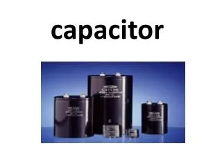
THE CAPACITOR UNIT AND BANK CONFIGURATION The Capacitor Unit • The capacitor unit, Fig. 3, is the building block of a shunt capacitor bank. • The capacitor unit is made up of individual capacitor elements, arranged in parallel/ series connected groups, within a steel enclosure. The internal discharge device is a resistor that reduces the unit residual voltage to 50V or less in 5 min.
SCB operation • The SCB of the line abosrbz leadind var (i.e generates lagging var). At the time of light load the lagging vars produced by the lines are much larger than that required by loads. These surplus lagging vars must be absorbeed by additional equipment to keep voltage profile within limits. • SCB are those reactive power compensating equipment to generate generate or absorb vars.
S=P+jQWhere,S=apparent power=VI(kva)Q=reactive power=VIsinФ(kvar)P=active power=VIcosФ(kw)
Capacitorunit capabilities • Relay protection of shunt capacitor banks requires some knowledge of the capabilities and limitations of the capacitor unit and associated electrical equipment including: individual capacitor unit, bank switching devices, fuses, voltage and current sensing devices. • Capacitors are intended to be operated at or below their rated voltage and frequency as they are very sensitive to these values; the reactive power generated by a capacitor is proportional to both of them (kVar ≈ 2π f V2 ).
Bank Configurations • The use of fuses for protecting the capacitor units and it location is an important subject in the design of SCBs. • They also affect the failure mode of the capacitor unit and influence the design of the bank protection. • Depending on the application any of the following configurations are suitable for shunt capacitor banks: • (1) externally fused • (2) internally fused • (3) fuseless shunt capacitor bank • (4) unfused shunt capacitor bank
Externally Fused • An individual fuse, externally mounted between the capacitor unit and the capacitor bank fuse bus, typically protects each capacitor unit. • The capacitor unit can be designed for a relatively high voltage because the external fuse is capable of interrupting a high-voltage fault. 3. A failure of a capacitor element welds the foils together and short circuits the other capacitor elements connected in parallel in the same group. 4. The remaining capacitor elements in the unit remain in service with a higher voltage across them than before the failure and an increased in capacitor unit current. 5. If a second element fails the process repeats itself resulting in an even higher voltage for the remaining elements. 6. Successive failures within the same unit will make the fuse to operate, disconnecting capacitor unit and indicating the failed one.
Internally Fused 3.. Banks employing internally fused capacitor units are configured with fewer capacitor units in parallel and more series groups of units than are used in banks employing externally fused capacitor units • Each capacitor element is fused inside the capacitor unit. • . Upon a capacitor element failure, the fuse removes the affected element only. The other elements, connected in parallel in the same group, remain in service but with a slightly higher voltage across them.
Fuseless Shunt Capacitor Banks The protection is based on the capacitor elements failing thus short- circuiting the group. When the capacitor element fails it welds and the capacitor unit remains in service. The voltage across the failed capacitor element is then shared among all the remaining capacitor element groups in the series. The capacitor units for fuseless capacitor banks are identical to those for externally fused described above. To form a bank, capacitor units are connected in series strings between phase and neutral, shown in Fig. 6. The discharge energy is small because no capacitor units are connected directly in parallel. Another advantage of fuseless banks is that the unbalance protection does not have to be delayed to coordinate with the fuses
Unfused Shunt Capacitor Banks Contrary to the fuseless configuration, where the units are connected in series, the unfused shunt capacitor bank uses a series/parallel connection of the capacitor units. The unfused approach would normally be used on banks below 34.5 kV, where series strings of capacitor units are not practical, or on higher voltage banks with modest parallel energy. This design does not require as many capacitor units in parallel as an externally fused bank.
CAPACITOR BANK DESIGN The protection of shunt capacitor banks requires understanding the basics of capacitor bank design and capacitor unit connections. The capacitors banks are arrangements of series/paralleled connected units. Capacitor units connected in paralleled make up a group and series connected groups form a single-phase capacitor bank. When a capacitor bank unit fails, other capacitors in the same parallel group contain some amount of charge. This charge will drain off as a high frequency transient current that flows through the failed capacitor unit and its fuse. The fuse holder and the failed capacitor unit should withstand this discharge transient.
The optimum connection for a SCB depends on the best utilization of the available voltage ratings of capacitor units,fusing, and protective relaying.Virtually all substation banks are connected wye. various types of SCB designs are: (1) Grounded wye-connection banks (2) Underground wye-connection banks (3) Delta connected banks
Grounded Wye-Connected Banks Grounded wye capacitor banks are composed of series and parallel-connected capacitor units per phase and provide a low impedance path to ground. Fig. 7 shows typical bank arrangements. Fig. 7 - Grounded Wye Shunt Capacitor Banks
Advantages of the grounded capacitor banks include: • Its low-impedance path to ground provides inherent self-protection for lightning surge currents and give some protection from surge voltages. • Offer a low impedance path for high frequency currents and so they can be used as filters in systems with high harmonic content. • Reduced transient recovery voltages for circuit breakers and other switching equipment Some drawbacks for grounded wye SCB are: • Increased interference on telecom circuits due to harmonic circulation 2. Circulation of inrush currents and harmonics may cause misoperation of protective relays and fuses
Ungrounded Wye-Connected Banks • Ungrounded wye banks do not permit zero sequence currents, third harmonic currents, or large capacitor discharge currents during system ground faults to flow. • Overvoltage appearing at the CT secondaries are not as high as in the case of grounded banks. However, the neutral should be insulated for full line voltage because it is momentarily at phase potential when the bank is switched or when one capacitor unit fails in a bank configured with a single group of units.
Delta-connected banks are generally used only at distributions voltages and are configured with a single series group of capacitors rated at line-to-line voltage. 2. With only one series group of units no overvoltage occurs across the remaining capacitor units from the isolation of a faulted capacitor unit. Delta-connected Banks
CAPACITOR BANK PROTECTION • The protection of SCB’s involves: • protection of the bank against faults occurring within the bank including those inside the capacitor unit • protection of the bank against system disturbances and faults.
Capacitor Unbalance Protection • The protective elements found in a SCB for internal faults are: individual fuses, unbalance protection to provide alarm/ trip and overcurrent elements for bank fault protection. 2. Removal of a failed capacitor element or unit by its fuse results in an increase in voltage across the remaining elements/ units causing an unbalance within the bank. 3. Unbalance protection normally senses changes associated with the failure of a capacitor element or unit and removes the bank from service when the resulting overvoltage becomes excessive on the remaining healthy capacitor units. 4.Unbalance protection normally provides primary protection for arcing faults within a capacitor bank and other abnormalities that may damage capacitor units
5. The unbalance protection should have minimum intentional delay in order to minimize the amount of damage to the bank in the event of external arcing. 6. The need for sensitive resulted in the development of unbalance protection where certain voltages or currents parameters of the capacitor bank are monitored and compared to the bank balance conditions. 7. Capacitor unbalance protection is provided in many different ways, depending on the capacitor bank arrangement and grounding.
Protection of the SCB Against System Disturbances and Faults System Overvoltage Protection The capacitor bank may be subjected to overvoltages resulting from abnormal system operating conditions. If the system voltage exceeds the capacitor capability the bank should be removed from service. The removal of the capacitor bank lowers the voltage in the vicinity of the bank reducing the overvoltage on other system equipment. Time delayed or inverse time delayed phase overvoltage relays are used.
Relays for Bank Closing Control Once disconnected from the system a shunt capacitor bank cannot be re-inserted immediately due to the electrical charge trapped within the capacitor units, otherwise catastrophic damage to the circuit breaker or switch can occur. To accelerate the discharge of the bank, each individual capacitor unit has a resistor to discharge the trapped charges within 5min.
CONCLUSIONS The protection of shunt capacitor banks uses simple, well known relaying principles such as overvoltage, overcurrents. Unbalance is the most important protection in a shunt capacitor bank, as it provides fast and effective protection to assure a long and reliable life for the bank. To accomplish its goal, unbalance protection requires high degree of sensitivity that might be difficult to achieve.