TRD Status Report – Octagon Integration and Electronics Developments (April 2006)
This report outlines the progress on the TRD Octagon Integration, detailing the completion of crucial components such as flight frontend boards and gas systems, along with functionality tests underway. Key achievements include the successful testing of all temperature sensors, installation of HV ground connections, and progress in gas-tower setup. It also presents the final report on TRD Front End Electronics, showcasing rigorous testing and calibration of UFE modules, confirming adherence to specifications and highlighting the achieved integration milestones as preparation for upcoming cosmic tests.

TRD Status Report – Octagon Integration and Electronics Developments (April 2006)
E N D
Presentation Transcript
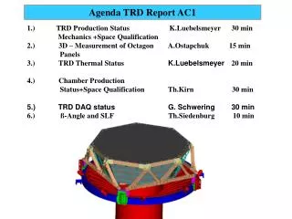
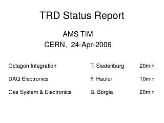
TRD Status Report AMS TIM CERN, 24-Apr-2006 Octagon Integration T. Siedenburg 20min DAQ Electronics F. Hauler 10min Gas System & Electronics B. Borgia 20min
Aachen TRD Status Report Th. Siedenburg AMS TIM CERN, 24-Apr-2006
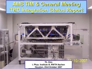
TRD Octagon Integration (Th.Kirn) 21-APR-2006 I. Özen
TRD Octagon Integration 21-APR-2006
TRD Octagon Integration • All DALLAS temperature sensors tested • All 82 flight frontend boards installed (UFE) • HV ground connections installed • UFE function tests in progress • Gas-tower interconnection tubes installedTower to tower finished next week • Gas-group cosmic tests in preparation • TRD upper plate: Installation of inserts • STA M-Structure machined within specs.Test mounting in preparation • TRD Rosengitter in preparationGastubing / Dallas & UFE cabeling
TRD Longterm Test 2 Years Gastightnessunchanged Gasgainstable J. Hattenbach
Final Report on TRD Front End ElectronicsUFE (Flight Modules)Ch.H. Chung
Production of UFE (FM) Integration + 358VA Chips Tests Select 202 Chips 101Production of 4 Types PCB Series of Space Qualification Tests Functional Tests TVT 3D Vibration Coating TVT
Space Qualification Tests Random Vibration X,Y and Z-Direction aRMS = 6.8g, 20-2000 Hz for 120 sec Functional test without failure 1st TVT Temperature : -40oC … +80oC Pressure : 110-5 mbar Functional test without failure 2nd TVT Same as 1st TVT condition Conformal Coating
Thermal Profile in TVT Operating Temperature (-20 ~ +50 oC) : Gain Calibration Points
Noise after SQT Noise = 1.5 ADC == ENC = 4000 e- Common mode noise corrected Pedestal RMS
Gain Calibration +50 oC -20 oC
Gain vs. Temperature All 6464 channels are calibrated over full Temperature range
Flight UFE Selection ALL 101 produced UFEs within specificationsSelect “better“ UFEs as flight modules
TRD-UFE (FM) Pedestal Distribution : ~ 10% of full range
TRD-UFE (FM) Noise RMS Spread : ~ 4%
TRD-UFE (FM) Gain RMS Spread : ~ 3% 25oC
TRD UFE Summary UFE(FM) Production : Finished (Jul. 2005) Total = 101 UFEs (FM = 82, FS = 19) Functional Tests : Finished (20.07.05) UFE Space Qualification Tests (Mar.05 ~ Mar. 06) 1st Thermal Vacuum Test = 101 (Done w/o failure) Random Vibration Test = 101 (Done w/o failure) Conformal Coating = 101 (Done w/o failure) 2nd Thermal Vacuum Test = 101 (Done w/o failure) Best 82 FMselected (Mar. 2006) UFE Integration : Finished (Apr. 2006)
TRD Gas Manifolds • Distribute TRD gasflow into 41 segments • Measure gastightness of individual segments • Allow isolation of a segment when leaky • Introduce no additional risk of gas leakage
OctagonTemperature Swing +30 R,P,Y hottest OHB TRD Thermal Report 240 days (4 b periods) eMLI = 0.03 Average TRD Temperaturebetween +35oC and -20oC Depending on ISS R, P, Y 0 R,P,Y coldest -20
Improve Manifold Leaktightness FVb FVa
● Dry mounting of all components● Full function test● Potting when ok New Manifold Prototype Alu. Body Viton Seal Alu. Cover
New Manifold Design Fits inside existing magnetic shielding Gas connectionswith double-o-ringfront access
Cold Case Flipper-Valve Operation Leakage to outside if switched below -8oC No switching below -15oC Buerkert 6124 Flipper-Valve Temperature TVT Tank Vacuum Viton Bag
FVa FVa+b FVb 18×10-5 3.4×10⁻⁵ l mbar/s 3.0×10⁻⁵ Helium Leakrate (1 Gasgroup 50×10-5 ) Manifold operation: heated switching Switching in TVT at -25oC ok if valve heated to 0oC Heating of fully potted 2FV manifold: 2 x 2W x 30 min. Gastightness through valves and to outside ok Heater powerline control (8H+8C 40W each) TBD SMD 100W
TRD Integration Schedule Octagon Integration finished in May 06Rosengitter tubing & cabeling Jun - Sep 06Manifold design & production Apr - Oct 06Box-S/C EM -> QM upgrade Apr - Jul 06UG QM Electronics Prod. & Test Apr - Oct 06Box-S/C FM Prod. & Test Apr - Dec 06TRD Cosmics EM UGcrate @ RWTH Nov - Dec 06TRD Cosmics QM UGcrate TBD Jan - Mar 07UG FM Electronics Prod. & Test Oct 06 - May 07