Mechanical Fastening Processes Brazing
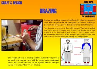
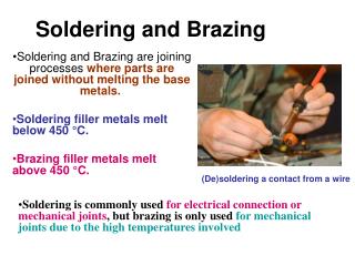
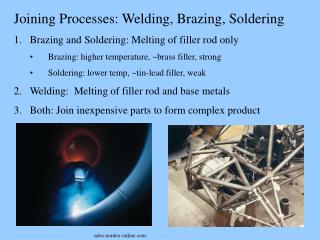
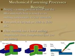
Mechanical Fastening Processes Brazing. Brazing – joining process where just the filler material’s heat is raised to its melting temperature to join materials First used as far back as 3000 to 2000 B.C. Filler material has a lower melting temperature than components that you are joining.

Mechanical Fastening Processes Brazing
E N D
Presentation Transcript
Mechanical Fastening ProcessesBrazing • Brazing – joining process where just the filler material’s heat is raised to its melting temperature to join materials • First used as far back as 3000 to 2000 B.C. • Filler material has a lower melting temperature than components that you are joining.
Mechanical Fastening ProcessesBrazing • Brazing uses a flux in order to prevent oxidation during the joining process • Factors that affect braze strength • Joint clearance • Joint area • The bond formed between the filler material and the base metal • Proper use of flux
BrazingVarious Methods • Torch – uses oxyfuel thru a torch • Furnace – parts preloaded with consumable inserts then placed in furnace for uniform heating • Induction – Heats thru use of High freq AC • Dipping – dips entire base material into molten filler metal bath (used for very small parts)
Mechanical Fastening ProcessesSoldering • Main difference between soldering and Brazing lies in Temperature. • Uses primarily tin-lead as filler material • Main use is for electronics which can’t withstand extreme heat of brazing. • Uses same techniques as brazing as well as that of Wave soldering – very useful for circuit boards.
Adhesive Bonding • Types of Adhesives • Natural adhesives-starch, dextrin, soya flour, and animal products • Inorganic Adhesives-sodium silicate and magnesium oxychloride • Synthetic organic adhesives-thermoplastics, thermosetting polymers (most important in manufacturing)
Adhesive Bonding • Electronically Conducing Adhesives • Developed to replace lead-based solder, added metal particles (40% to 70%) • Used in electronics such as calculators, TVs, and LCDs
Adhesive BondingSurface Prep, Process Capabilities, and Applications • Surface Preparation • Surface must be free of dirt, dust, oil and any other contaminants • Porous or rough surface is desirable, improve adhesion • Process Capabilities • Used to bond metallic and non-metallic material • Do not subject to peeling
Adhesive BondingSurface Prep, Process Capabilities, and Applications • Applications • Used in most industries • Allows bond between dissimilar metals and reduces vibration and noise • Distributes the load eliminating local stresses that usually result from mechanical fasteners • External appearance is unaffected • Thin and fragile components can be bonded without weight increase
Adhesive BondingDesign for Adhesive Bonding • Ensure that joints are subjected only to compressive, tensile, and shear forces, not to peeling or cleavage
Mechanical Fasteners • Preferred over other methods because of the following: • Ease of manufacturing • Ease of assembly and transportation • Ease of disassembly, maintenance, part replacement, or repair • Ease in creating designs that have movable joints • Lowers cost
Mechanical Fasteners • Hole Prep • Using different methods to create the hole produces different characteristics • Hole with some residual stress is desirable, improves fatigue life • Threaded Fasteners • Common bolts and screws • Rivets • Most common method of permanent and semipermanent mechanical joining • Works by placing rivet through hole and deforming end
Mechanical Fasteners • Other Fastening Methods • Metal Stitching and stapling • Similar to ordinary stapling • Seaming • Folding two pieces of material together • Crimping • Physically forcing on piece onto another • Design • Use fewer, but larger, rather than many small • Fit between joined parts • Use standard sizes and keep holes away from edges or corners
Joining Plastics, Ceramics, and Glasses • Joining Thermoplastics • Thermal Methods • Using heat to soften or melt two pieces at the interface to ensure good bond • Many way to apply the heat • Adhesive Bonding • Uses adhesives previously discussed to attach the plastics • Joining Thermosets • Joined using threads, mechanical fasteners, solvent bonding, co-curing and adhesive bonding
Joining Plastics, Ceramics, and Glasses • Joining Ceramics and Glasses • Ceramics • Treat surface with coating that is easily bonded • Braze tungsten carbide and titanium carbide • Join during their primary shaping process • Glasses • Are bonded easily • Done by softening and pressing two pieces together and cooling • Can be bonded to metals due to diffusion of metal ions into the glass sturcture.
32.7 Economics of Joining Ops • Cost from highest to lowest of various Joining Operations Highest:Brazing, bolts, nuts, and other fasteners. Intermediate:Riveting and adhesive Low:Seaming and crimping
Closer look at Brazing Costs • Manual Brazing: • Basic equipment costs $300 • $50,000+ for automated systems • Furnace Brazing: • Wide range from $2,000 for batch furnaces to $300,000 for continuous vacuum furnaces. • Induction Brazing: • $10,000 for small units
Closer look at Brazing Costs • Resistance Brazing: • $1,000 for simple units • $10,000+ for larger units • Dip Brazing • $2,000 to $200,000+, depends on equipment which may be computer controlled • Infrared Brazing: • $500 to $30,000 • Diffusion Brazing: • $50,000-$300,000
Closer look at Brazing Costs High End Convection CAB Brazing Furnace High End Vacuum Furnace
Surface Technology • How do we react to surfaces? • Touch • Roughness • Texture • Scratches • Sight • Waviness • Color • Reflectivity
Surface Technology • Jargon: “Surface Integrity”Describes the physical, chemical and mechanical characteristics of surfaces • Influences on surfaces • Friction and wear of tools, molds, dies and of the products themselves. • Effectiveness of lubricants during manufacturing and throughout the products life. • Thermal and electrical conductivity of contacting bodies.
Surface Technology • Influences on surfaces (cont.) • Appearance and geometric features of the part and their role in subsequent operations, such as welding, soldering, adhesive bonding, painting, coating and corrosion. • Crack initiation as a result of surface defects like roughness, scratches, seams, and heat–affected zones. These can lead to weakening and premature failure of a part.
Chapter 33 Surface Roughness and Measurements of Friction, Wear and Lubircation 33.2 Surface Structure and Integrity • Metal surfaces generally contain several layers • 1ST Layer:Bulk Metal (substrate) has a structure that depends on the composition and processing history. • 2ND Layer:Above the bulk metal is “Surface Structure” that is plastically deformed and work hardened more so than the Bulk Metal. The depth & properties of this layer depend on processing method and friction.
33.2 Surface Structure and Integrity • 3RD layer: Is the “Oxide Layer.” The only way to avoid this is to keep the metal in an oxygen free environment or work with a noble metal (gold, platinum). • 4TH layer: is the “Absorbed Layer.” This layer absorbs gas and moisture. • 5TH layer: Is the outermost layer that may be covered with contaminants such as dirt, dust, grease, various residues and other environmental pollutants.
Surface Integrity • Surface integrity describes topological, physical, and chemical as well as their mechanical, metallurgical properties and characteristics. Various surface defects can weaken the Sruface Integrity • Cracks: internal, external and microscopic • Craters: shallow depressions • Heat-affected zones
Surface Integrity • Surface Defects (continued) • Inclusions:small nonmetallic elements • Intergranular attack:the weakening of grain boundaries • Laps, Folds and Seams:overlapping of material during processes • Metallurgical transformations:microstructural changes caused by temperature cycling of the material • Pits: shallow surface depressions from chemical or physical attack
Surface Integrity • Surface Defects (continued) • Residual stresses: Either by tension or compression and causes nonuniform deformation and temperature distribution. • Splatter:Small resolidified molten metal particles on the surface. • Surface Plastic deformation: Severe surface deformation caused by high stress from friction, tool and die geometry, worn tools, and processing methods.
33.3 Surface Texture and Roughness • Surface Texture are characteristics that define a surface. These can be separated into four categories which are: • Flaws or defects: random irregularities, such as scratches, cracks, holes, depressions, seams, tears, or inclusions • Lay (directionality): direction of the predominant surface pattern • Roughness: closely spaced, irregular deviations on a small scale • Waviness: recurrent deviation from a flat surface • Surface roughness is usually described in two ways: • Arithmetic mean value (R a) – the schematic illustration of a rough surface • Root-mean roughness height – was known as RMS • Maximum roughness height (R t) – the height from the deepest trough to the highest peak; indicates how much material has to be removed to obtain a smooth surface
Coordinates used for surface-roughness measurements R a = ( a + b + c + d + ….)/ n R q = sq rt [(a2 + b2 + c2 + d2 + ….)/n]
Standard terminology and symbols used to describe surface finish Some symbols used to represent surface finish
Measuring Surface Roughness When measuring surface roughness, instruments called surface profilometers are used. Profilometers are tipped with a diamond stylus which usually has a 10 micon diameter. The way profilometers are used is they travel over the surface in a straight line recording about 10 to 15 roughness irregularities. The distance travel maybe anywhere from .08 to 25 mm. The most common distance used is .8 mm.
3d surface measurement There are other ways of measuring surface measurement. This is done by using either an Optical-interference microscope or an atomic-force microscope. • Optical-interference microscopes: shine a light against a reflective surface and record the interference fringes that result from the incident and its reflective waves • Atomic-force microscopes (AMFs): it’s a very fine surface profilometer with a laser.
33.4 Friction • There are several theories that explain friction. Two of the more commonly accepted theories are the adhesion theory and the abrasion theory. • Adhesion theory: theory that states that the contact of two items is actually only a fraction of their apparent contact area. • Abrasion Theory: theory that states that the asperities of a harder surface penetrates and plows through a softer surface. Another thing to take in to account is that all friction dissipates energy. This energy is converted into heat. Sometimes the heat may soften or even melt the material in use
Plastics and Ceramics Plastics generally possess low frictional characteristics. This is better for creating items such as bearings, gears, seals, prosthetic joints. But, an important consideration is that plastics have a low melting point. So, any heat caused by friction must be taken into account. Ceramics on the other hand have generally the same frictional characteristics as metals.
Reducing friction • Some ways of reducing friction are : • Selection of materials used • Lubricants or solid films (such as graphite) • Ultrasonic vibrations
Frictional measurement The coefficient of friction is found during the manufacturing process or in laboratory tests using smaller versions of various sizes of the material. One of the common tests used is called the ring-compression test. This is where a flat ring is upset plastically between two flat platens. If the both the diameters of the ring expand outward then the friction is zero. If the inner diameter becomes smaller, then there’s an increase of friction.
33.5 Wear Wear changes the shapes of tools and dies, affects the tool life, tool size, and the quality of the parts produced. Importance of wear is evident in the number of parts and components that continually have to be replaced or repaired. i.e. dull drill bits, worn cutting tools and dies
33.5 Wear Running In period removes the peaks from asperities. Under controlled conditions, wear may be regarded as a type of smoothing or polishing process.
Adhesive Wear A tangential force is applied and shearing takes place either at a) the original interface b) along a path below or above the interface *adhesive bonds often are stronger than the base metals. Schematic illustration of (a) two contacting asperities, (b) adhesion between two asperities, and (c) the formation of a wear particle.
Abrasive Wear Caused by a hard rough surface sliding across another surface. Microchips and slivers are produced, leaving grooves or scratches on the softer surface. *processes: filing, grinding, ultrasonic machining and abrasive jet machining act in this manner
Other types of Wear • Corrosive. • Fatigue-when the surface of a material is subjected to cyclic loading • Erosion-caused by loose abrasive particles on a surface • Fretting • Impact
33.6 Lubrication 4-Regimes of Lubrication in Manufacturing Ops. 1)Thick-film: surfaces separated completely by a film of lubricant. Results in dull, grainy surface appearance after forming operations 2) Thin-film: Load between the die and work piece increases, or the speed and viscosity of fluid decrease, the lubricant becomes thinner raising friction and results in slight wear
33.6 Lubricants 3)Mixed: a significant portion of the load is carried by the physical contact of the two surfaces. The rest is carried by the fluid film trapped in the valleys (asperities). 4) Boundary: load supported by contacting surfaces covered with boundary film of lubricant. The lubricant is attracted physically to the metal surfaces, thus preventing direct metal-to-metal contact and reducing wear.
33.7 Metalworking Fluids • Reduce friction • Reduce wear • Improve material flow • Act as a thermal barrier between the workpiece and its tool and die surfaces • Act as a release or parting agent
Oils and Emulsions Oils are very effective in reduction of friction and wear and have low thermal conductivity but they do not conduct away the heat generated by friction effectively. *It is difficult and costly to remove oils from component surfaces that are to be painted or welded, and is difficult to dispose of. Emulsion: mixture of oil and water in various proportions along with additives. aka water-soluble oils or coolants 1)direct: mineral oil dispersed in water in very small droplets Important in metalworking b/c the presence of water gives them high cooling capacity.