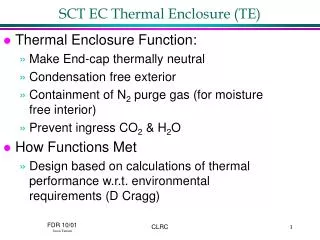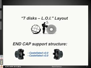
SCT EC Support Structure
SCT EC Support Structure. Support Structure. SCT EC Support Structure. Cylinder, Wings & In-Fill Panels. SCT EC Support Structure. Requirements Strength to Support 9 Wheels, Services & Thermal Enclosure. Maintain Module Positions in Long & Short Term (Defined in ATL-IS-ER-0027)

SCT EC Support Structure
E N D
Presentation Transcript
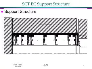
SCT EC Support Structure • Support Structure CLRC
SCT EC Support Structure • Cylinder, Wings & In-Fill Panels CLRC
SCT EC Support Structure • Requirements • Strength to Support 9 Wheels, Services & Thermal Enclosure. • Maintain Module Positions in Long & Short Term (Defined in ATL-IS-ER-0027) • Low Mass & Radiation Length Construction • Maintain External Dimensions that Remain Within Defined Envelope (0-TB-0049-177-01) • Radiation Tolerance to 0.24MGy CLRC
SCT EC Support Structure • Envelope Figures reproduced from: 0-TB-0049-177-01 CLRC
SCT EC Support Structure • Actual Sizes CLRC
SCT EC Support Structure • Manufacturing & Assembly Tolerances • Deviation of final component size from nominal (within tolerance) • Accuracy of alignment when assembling components • Deformation of components during assembly (mainly Wheels & Services) • Accuracy of integration with TRT • Accuracy of Squirrel Cage Mount Rails w.r.t. nominal beamline CLRC
SCT EC Support Structure • Adjustments to Reduce Effects of M&A • Wheel (& attached modules) Aligned With Disc Fixings • Sag in Cylinder • Averaging Out Locations of Module Rings • Averaging Out Component Assembly Misalignment • Wing Couplings (Shimmed & Slotted) • Adjust Relative to Squirrel Cage & Cryostat • Averaging Out Component Assembly Misalignment CLRC
SCT EC Support Structure • x,y,z Coupling CLRC
SCT EC Support Structure • Acclimatisation & Run-In • Thermal Contractions upon cool-down • Effects of moisture desorption in dry atmosphere • In Service Deformation • Local excitation where structures position affected • Variation in ambient temperature and effect on structural size • Long term creep effects • ‘One-off’ excitations where structural position affected CLRC
SCT EC Support Structure • Short Term Stability • From ATL-IS-ER-0027, required stability in 1 day; • z = 200m • r = 50m • r- = 50m • Short term instability from, Excitation/CTE (CME after acclimatisation << 10m in any direction / day) • Calculated • z = 52m @ W1 (worst case) • r = 9m (x), < 3m (y) (not incl. external input) • r- = 10m (x + 10%), no twist, (not incl. external input) CLRC
SCT EC Support Structure • Low Mass & Radiation Length • Design optimisation through FEA to ensure minimal use of material • Use of high stiffness to weight composite structures & materials CLRC
SCT EC Support Structure • Radiation Resistance • Materials Verified; • XN-50A/RS-3 5x10⁷ Gy TD(CERN TIS 98-01, 18/5/98, Compilation of Radiation Damage Test Data, Tavlet M et al.) • RS-3 unfilled slight effect up to 107 Gy, RS-4A similar composition so no expected problems (same ref. as above) • Nomex 107 Gy TD, very similar to Korex so no expected problems (CERN TIS 82-10, 4/11/82, Compilation of Radiation Damage Test Data,Beynel P et al.) • Metallics, no expected problems. CLRC
SCT EC Support Structure • Support Cylinder CLRC
SCT EC Support Structure • Support Cylinder Continued… • Typical sandwich cross section CLRC
SCT EC Support Structure • Rear Wing CLRC
SCT EC Support Structure • Rear Wing Continued… • Typical sandwich cross section CLRC
SCT EC Support Structure • Front Wing CLRC
SCT EC Support Structure • Front Wing Continued • Typical Cross Section CLRC
SCT EC Support Structure • In-Fill Panels CLRC
SCT EC Support Structure • Conclusion • Support Structure size adjusted from envelope size to account for likely deformations • Manufacture & assembly tolerances adjusted out via disc fixings wing couples, acclimatisation adjustments possible too • Support Structure materials chosen for structural ‘ability’, environmental stability and radiation length characteristics CLRC
SCT EC Support Structure • Conclusion Continued… • Overall component shapes defined by; • Envelopes • Structural requirements (through analysis & prototyping) • Interactions with components and with assembly / integration procedures. • Based on components shapes that have been successfully prototyped (prototype Barrel Cylinder & prototype Rear Wing). CLRC
SCT EC Support Structure • Cradled EC Concept CLRC