Tribology Lecture II Elastohydrodynamic Lubrication
740 likes | 3.06k Vues
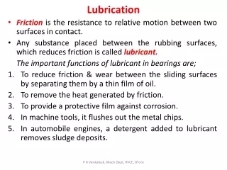
Tribology Lecture II Elastohydrodynamic Lubrication. Hydrodynamic Lubrication. w. Fluid Layer. p. Pressure required to support the load is generated by motion and geometry of the bearing in concert with the viscosity of the lubricant. Hydrodynamic Lubrication. w. Fluid Layer. p.

Tribology Lecture II Elastohydrodynamic Lubrication
E N D
Presentation Transcript
Hydrodynamic Lubrication w Fluid Layer p Pressure required to support the load is generated by motion and geometry of the bearing in concert with the viscosity of the lubricant
Hydrodynamic Lubrication w Fluid Layer p Pressure is generated by motion and geometry of the bearing in concert with the viscosity of the lubricant
U Hydrodynamic LubricationPoint Contact w Sphere R Fluid Layer hc
Hydrodynamic Lubrication(Refinement: Both surfaces moving) w Sphere R U1 Fluid Layer hc U2 “Entrainment” or “Rolling Velocity”
Hydrodynamic Lubrication(Refinement: two spheres) w R1 U1 hc U2 Where R is now “reduced” radius R2
Hydrodynamic Lubrication w R1 • Nice theory but as a rule it • greatly under estimates hc • Pressure is very high near contact • P >>1000atm ( 108 Pa) • Pressure Dependence of • Elastic Deformation of Sphere U1 hc U2 R2
Pressure and Temperature Dependence of Viscosity Viscosity increases exponentially with pressure: Barus Equation: pressure viscosity coefficient 0 (cp) SAE 10 266 2.51x10⁻⁸ SAE 30 1053.19x10-8
Large stresses lead to elastic deformation w w R1 R1 R2 R2 Contact Circle (radius a) Contact Point Conformal Contact Point Contact
Large stresses lead to elastic deformation w w R1 R1 R2 R2 Contact Circle (radius a) Contact Point Conformal Contact Point Contact
Elastic Deformation of Sphere w R1 R is the reduced radius E* contact modulus 2a R2
E1 E1 E1 E2 E2 E2 E2>>E1 E1>>E2 • Either way contact becomes conformal
Because of rise in viscosity with pressure deformation is about the same with the lubricating fluid present E1 E1 hc E2 E1 hc E2 • Surfaces are parallel at contact - i.e. “conformal” • Lower E* ( larger a for same load ) larger hc
Elastohydrodynamic Lubrication (EHD L) w To variables for hydrodynamic lubrication E1 U1 add hc E2 U2 • How does hc depend on these parameters?
Elastohydrodynamic Lubrication (EHD L) Dimensional Analysis speed load material Hamrock & Dowson Equation • Dependence on load is very weak 2.067=1.048
Hamrock & Dowson Equation (clarification from lab manual) where u = rolling velocity OIL= zero pressure oil viscosity, = oil viscosity at higher pressure = pressure-viscosity index from the equation, = OILexp(P) Note factor of 2
Tribology Lab • Measure hc as a function of U and W • Compare result with Hamrock Dowsen equation
ME 4053 Tribology Lab • Objectives: Characterize elastohydrodynamic (EHD) lubrication using an optical technique. The study involves: • Measurement of the lubricating film thickness as a function of: • rolling velocity • normal load • Comparison of the measured film thickness with a theoretical film thickness (from the Hamrock & Dawson equation) • Experimental Setup: Light Source: Camera Monitor Camera Light Source aperture Semi- reflective Surface Loading Mechanism Nd Glass plate (connected to motor) Steel ball Fiberoptic Cable condenser Contact Area
Experimental Setup (cont’d) Camera Light Beam side view: top view: Nd glass disc u oil film rc Fringe pattern h W(load) Nd: rpm; u: rolling velocity; h: film thickness Rolling velocity: Measured oil film thickness: , where: : wavelength of light in air (600nm) N: fringe order n: refractive index of oil (1.5) : phase shift constant (0.1)
Experimental Procedure: obtain the following table for W=16N & W=30N computed from Nd, N computed from HD equation measured Theoretical Thickness, ht: The Hamrock & Dowson Equation R: ball radius W*: dimensionless load parameter U*: dimensionless speed parameter G*: dimensionless material parameter
Results Presentation: Theoretical/Experimental Comparison: ln(h/R) ln(U*) *Practical note on load adjustment: Load = 2 x (spring value - tare value) (tare = 3.2N) Ex: to get W=16N, set spring value to 11.2N 16 = 2 x (11.2 - 3.2)