Download
1 / 17
170 likes | 204 Vues
Explore the highlights of the 2004 Beam Instrumentation Workshop where physicists and engineers gathered to exchange ideas and review instrumentation designs. The program included tutorials on EMI grounding, beam diagnostics, and FPGA-based instrumentation. Invited talks covered SNS overview and instrumentation systems. Participants discussed beam diagnostics and toured the SNS facility in Knoxville, TN. Discover the award-winning Faraday Cup design and the latest advancements in accelerator instrumentation.

E N D
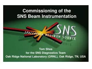
Highlights of the 2004 Beam Instrumentation Workshop Arne Freyberger, John Musson, Chris Tennant Beam Physics Seminar Jefferson Laboratory May 21st, 2004 (Photo Chris Tennant, JLab)
2004 Beam Instrumentation Workshop Where: Knoxville, TN When: May 3 – 6, 2004 Who: Physicists and Engineers (107 attendees) Why:“To exchange ideas and review instrumentation designs and to serve as an introduction to relevant topics for engineers and scientists with the aid of tutorial sessions.” Program Included: 1 Faraday Cup Talk 3 Tutorials 4 Invited Talks (1) 15 Contributed Talks (2) 44 Posters Discussion Groups Tour of the SNS Facility Knoxville, TN (Visit http://www.SNS.gov/BIW04 to view oral presentations) (Photo Chris Tennant, JLab)
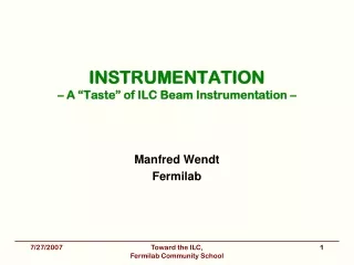
2004 Beam Instrumentation Workshop(cont’d…) • Faraday Cup Award • “…recognizes and encourages innovative achievements in accelerator and beam instrumentation” • And the 2004 Faraday Cup Award goes to… T. Mitsuhashi (KEK) • Tutorials • “Electromagnetic Interference (EMI) Grounding for Beam Diagnostics”M. Thuot (LANL) • “Interceptive Beam Diagnostics – Signal Creation and Materials Interactions”M. Plum (SNS) • “Tutorial on FPGA-Based Instrumentation and Beam Feedback”G. Foster (FNL) • Invited Talks (a personal selection) • “Overview of the SNS and its Beam Diagnostics Systems”T. Shea (SNS) • “Instrumentation Systems from an Operations Viewpoint”R. Mau (FNL)
2004 Beam Instrumentation Workshop(cont’d…) • Poster Session • “Beam Diagnostics for the BNL Energy Recovery Linac Test Facility” P. Cameron, et. al. (BNL) • “Transverse Feedback for the Electron-Cooled DC Beam at COSY” V. Kamerdzhiev, et. al. (FZJ) • Discussion Groups (my personal impressions) • Tour of the SNS Facility… • they can easily become dominated by a few individuals • they can lack an expert or someone to lead the discussion
SNS Conceptual Design (Courtesy of Tom Shea, ORNL)
805 MHz 402.5 MHz HEBT To Ring RFQ CCL SRF, b=0.61 DTL SRF, b=0.81 1000 MeV 387 MeV 186 MeV Injector 86.8 MeV 2.5 MeV 1 RFQ 6 DTL Tanks 4 CCL Modules 11 Medium-b Cryomodules - 3 Nb cavities each 12 High-b Cryomodules - 4 Nb cavities each Major SNS Facility Parameters 1.0 GeV Ring Up to 1.3 GeV Mercury Target (Courtesy of Tom Shea, ORNL)
SNS Diagnostics Deployment MEBT 6 Position 2 Current 5 Wires [2 Thermal Neutron]—9/04 [3 PMT Neutron] —9/04 1 Emittance [1 fast faraday cup]—9/04 1 faraday/beam stop D-box video D-box emittance –9/04 D-box beam stop D-box aperture Differential BCM [laser prototype]—9/04 RING 44 Position 2 Ionization Profile 70 Loss 1 Current 5 Electron Det. 12 FBLM 2 Wire 1 Beam in Gap 2 Video 1 Tune Operational IDump 1 Position 1 Wire 1 Current 6 BLM FY04 New to 2004 New to FY04 EDump 1 Current 4 Loss 1 Wire CCL 10 Position 9 Wire 8 Neutron 48 Loss 3 Bunch 1 Faraday Cup 1 Current ½ Laser in 04 FY2004/5 RTBT 17 Position 36 Loss 4 Current 5 Wire 1 Harp 3 FBLM DTL 10 Position 5 Wire 12 Loss 5 Faraday Cup 6 Current 6 Thermal and 12 PMT Neutron SCL 32 Position 86 Loss 8 Laser Wire 7 PMT Neutron HEBT 29 Position 11 Wire 46 BLM, 3 FBLM 4 Current LDump 6 Loss 6 Position 1 Wire CCL/SCL Transition 2 Position 1 Wire 1 Loss 1 Current (Courtesy of Tom Shea, ORNL)
Front End Diagnostic Systems Commissioned spring 2002 The Front End accelerates H- ions to 2.5 MeV Five diagnostic systems, all prototypes of linac/ring systems provided by LBNL, LANL, BNL, ORNL: 1 Emittance System 2 Beam Current Monitors 6 Beam Position Monitors 5 Carbon Wire Scanners 1 Laser Profile (Test) Ion Source (Photo Daryl Oshatz, LBNL) (Photo Chris Tennant, JLab) (Courtesy of Tom Shea, ORNL)
Drift Tube Linac (DTL) • Accelerates ion beam from 2.5 MeV to 87 MeV • 6 Tanks Total – the first three are installed in the tunnel Drift Tubes DTL 1 in the tunnel (Courtesy Eugene Tanke) (Courtesy of Tom Shea, ORNL)
DTL1 Results: Example Measurements Current (toroids) Position, phase Loss (ion chambers) emittance Current (MEBT beam stop) Current (DTL Faraday cup) Loss (neutron) Profile (wires) Current (D-plate beam stop) Bunch shape Halo (Courtesy of Tom Shea, ORNL)
Coupled-Cavity Linac (CCL) Plan September 2004 commissioning start Klystrons installed Tune cavities using a hammer! CCL Modules 1 & 2 in SNS Tunnel (Courtesy of Tom Shea, ORNL)
Superconducting Linac (SCL) • SRF cavities accelerate ion beam from 200 MeV to 1000 MeV • Commissioning Planned for March 2005 (Photo Chris Tennant, JLab) Medium-Beta Cryostat SCL Klystrons (Courtesy of Tom Shea, ORNL)
Peak detector Electron Coll. Toroid 2 Integrator Magnet Toroid 1 The SNS Laser Beam Profile Monitor • Motivation • Need an alternative to placing conventional (Carbon) wire scanners in the Superconducting Linac (SCL) region. • The concern is that by using wire scanners near SRF cavities one risks contaminating cavity surfaces (via actuator mechanisms, hot wire, breaking wires, etc…) • How it Works1 • A laser beam is directed transversely through the H- beam neutralizing a small portion • A downstream dipole is used to direct the released electrons to an electron collector • A profile measurement is generated by scanning the laser beam across the H- beam and measuring the electron beam current 1“The SNS Laser Profile Monitor Design and Implementation”, PAC 2003 (p. 2706) (Courtesy of Mike Plum, ORNL)
The SNS Laser Beam Profile Monitor (cont’d…) “Laser Beam-Profile Monitor Development at BNL for SNS”, LINAC 2002 (p. 21) • Advantages of using a “Laser Wire” • Profiles can be measured on high power beams • There are no moving parts within the vacuum system Neutralize 10ns of H- beam with Q switched Nd:YAG laser. Measure beam current notch with toroid. Cable and installation - BNL Laser system – BNL Beam box - LBNL Electronics, software – BNL,ORNL (Courtesy of Tom Shea, ORNL)
Accumulator Ring Diagnostics Layout • BNL is responsible for the accumulator ring which prepares the ion beam for delivery to the mercury target to produce neutrons • A carbon foil is used to strip the ion beam at the injection point to produce the protons that circulate the ring • After about 1000 accumulated turns, beam is extracted in one turn and travels down the Ring To Beam Target (RTBT) line. Note apertures From Linac To Target (Courtesy of Tom Shea, ORNL)
Diagnostics in One Section Downstream RF Section Electron Detector Side View (Courtesy of Tom Shea, ORNL)
The SNS Liquid Mercury Target • ORNL is responsible for the design and construction of the liquid mercury target. • “The SNS will be the first scientific facility to use pure mercury as a target for a proton beam”1(1.4 MW) Core Vessel and Shielding 1http://www.sns.gov/aboutsns/source.htm (Courtesy of Tom Shea, ORNL)