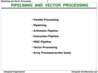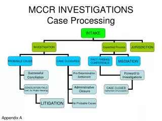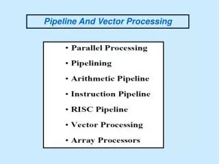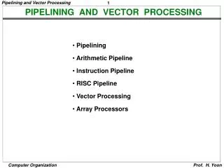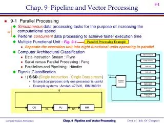
Pipeline and Vector Processing (Chapter2 and Appendix A) part2
Pipeline and Vector Processing (Chapter2 and Appendix A) part2. Dr. Bernard Chen Ph.D. University of Central Arkansas Spring 2010. Instruction-level parallelism (ILP). There are two largely separable approaches to exploiting ILP:


Pipeline and Vector Processing (Chapter2 and Appendix A) part2
E N D
Presentation Transcript
Pipeline and Vector Processing(Chapter2 and Appendix A) part2 Dr. Bernard Chen Ph.D. University of Central Arkansas Spring 2010
Instruction-level parallelism (ILP) • There are two largely separable approaches to exploiting ILP: • Hardware, to help discover and exploit the parallelism dynamically at run time • Software, find parallelism statically at compile time
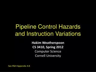
Pipeline Hazards • There are situations, called hazards, that prevent the next instruction in the instruction stream from executing during its designated cycle • There are three classes of hazards • Structural hazard • Data hazard • Branch hazard
Pipeline Hazards • Structural hazard • Resource conflicts when the hardware cannot support all possible combination of instructions simultaneously • Data hazard • An instruction depends on the results of a previous instruction • Branch hazard • Instructions that change the PC
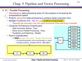
Structural hazard • Some pipeline processors have shared a single-memory pipeline for data and instructions
S1 1 2 3 4 5 6 7 8 9 S2 1 2 3 4 5 6 7 8 S3 1 2 3 4 5 6 7 S4 1 2 3 4 5 6 S5 1 2 3 4 5 Structural hazard Memory data fetch requires on FI and FO S1 S2 S3 S4 S5 Fetch Instruction (FI) Decode Instruction (DI) Fetch Operand (FO) Execution Instruction (EI) Write Operand (WO) Time
Structural hazard • To solve this hazard, we “stall” the pipeline until the resource is freed • A stall is commonly called pipeline bubble, since it floats through the pipeline taking space but carryin no useful work
Structural hazard Fetch Instruction (FI) Decode Instruction (DI) Fetch Operand (FO) Execution Instruction (EI) Write Operand (WO) Time
Data hazard Example: ADD R1R2+R3 SUB R4R1-R5 AND R6R1 AND R7 OR R8R1 OR R9 XOR R10R1 XOR R11
Data hazard FO: fetch data value WO: store the executed value S1 S2 S3 S4 S5 Fetch Instruction (FI) Decode Instruction (DI) Fetch Operand (FO) Execution Instruction (EI) Write Operand (WO) Time
Data hazard • Delay load approach inserts a no-operation instruction to avoid the data conflict ADD R1R2+R3 No-op No-op SUB R4R1-R5 AND R6R1 AND R7 OR R8R1 OR R9 XOR R10R1 XOR R11
Data hazard • It can be further solved by a simple hardware technique called forwarding (also called bypassing or short-circuiting) • The insight in forwarding is that the result is not really needed by SUB until the ADD execute completely • If the forwarding hardware detects that the previous ALU operation has written the register corresponding to a source for the current ALU operation, control logic selects the results in ALU instead of from memory
Loop • The simplest and most common way to increase ILP is to exploit parallelism among itera • For example: for (i=1000; i>0; i--) x[i] = x[i] + s • In this example, complier can help!!
Loop • If we translate the code into assembly language: Loop: LD F0, 0(R1) #F0: array element ADD F4, F0, F2 #F2 = S value SD 0(R1), F4 #store result SUB R1,R1,-1 #decrement BNE R1,R2,Loop #branch if R1!=R2(1)
Loop • Without scheduling, it takes 8 cycles Loop: LD F0, 0(R1) 1 stall2 ADD F4, F0, F2 3 stall 4 SD 0(R1), F4 5 SUB R1,R1,-1 6 stall 7 BNE R1,R2,Loop 8
Loop • If we schedule… Loop: LD F0, 0(R1) 1 stall2 ADD F4, F0, F2 3 stall 4 SD 0(R1), F4 5 SUB R1,R1,-1 6 stall 7 BNE R1,R2,Loop 8
Loop • After the scheduling, it takes only 6 cycles Loop: LD F0, 0(R1) 1 SUB R1,R1,-1 2 ADD F4, F0, F2 3 stall 4 SD 0(R1), F4 5 BNE R1,R2,Loop 6
Branch hazards • Branch hazards can cause a greater performance loss for pipelines • When a branch instruction is executed, it may or may not change the PC • If a branch changes the PC to its target address, it is a taken branch • Otherwise, it is untaken
Branch hazards • There are FOUR schemes to handle branch hazards • Freeze scheme • Predict-untaken scheme • Predict-taken scheme • Delayed branch
5-Stage Pipelining S1 1 2 3 4 5 6 7 8 9 S2 1 2 3 4 5 6 7 8 S3 1 2 3 4 5 6 7 S4 1 2 3 4 5 6 S5 1 2 3 4 5 Fetch Instruction (FI) Decode Instruction (DI) Fetch Operand (FO) Execution Instruction (EI) Write Operand (WO) Time
Branch Untaken (Freeze approach) • The simplest method of dealing with branches is to redo the fetch following a branch Fetch Instruction (FI) Decode Instruction (DI) Fetch Operand (FO) Execution Instruction (EI) Write Operand (WO)
Branch Taken (Freeze approach) • The simplest method of dealing with branches is to redo the fetch following a branch Fetch Instruction (FI) Decode Instruction (DI) Fetch Operand (FO) Execution Instruction (EI) Write Operand (WO)
Branch Taken (Freeze approach) • The simplest scheme to handle branches is to freeze the pipeline holding or deleting any instructions after the branch until the branch destination is known • The attractiveness of this solution lies primarily in its simplicity both for hardware and software
Branch Hazards(Predicted-untaken) • A higher performance, and only slightly more complex, scheme is to treat every branch as not taken • It is implemented by continuing to fetch instructions as if the branch were normal instruction • The pipeline looks the same if the branch is not taken • If the branch is taken, we need to redo the fetch instruction
Branch Untaken (Predicted-untaken) Fetch Instruction (FI) Decode Instruction (DI) Fetch Operand (FO) Execution Instruction (EI) Write Operand (WO) Time
Branch Taken (Predicted-untaken) Fetch Instruction (FI) Decode Instruction (DI) Fetch Operand (FO) Execution Instruction (EI) Write Operand (WO)
Branch Taken(Predicted-taken) • An alternative scheme is to treat every branch as taken • As soon as the branch is decoded and the target address is computed, we assume the branch to be taken and begin fetching and executing the target
Branch Untaken (Predicted-taken) Fetch Instruction (FI) Decode Instruction (DI) Fetch Operand (FO) Execution Instruction (EI) Write Operand (WO)
Branch taken (Predicted-taken) Fetch Instruction (FI) Decode Instruction (DI) Fetch Operand (FO) Execution Instruction (EI) Write Operand (WO)
Delayed Branch • A fourth scheme in use in some processors is called delayed branch • It is done in compiler time. It modifies the code • The general format is: branch instruction Delay slot branch target if taken
Delayed Branch • Optimal
Delayed Branch If the optimal is not available: (b) Act like predict-taken (in complier way) (c) Act like predict-untaken (in complier way)
Delayed Branch • Delayed Branch is limited by • (1) the restrictions on the instructions that are scheduled into the delay slots (for example: another branch cannot be scheduled) • (2) our ability to predict at compile time whether a branch is likely to be taken or not (hard to choose (b) or (c))
Branch Prediction • A pipeline with branch prediction uses some additional logic to guess the outcome of a conditional branch instruction before it is executed
Branch Prediction • Various techniques can be used to predict whether a branch will be taken or not: • Prediction never taken • Prediction always taken • Prediction by opcode • Branch history table • The first three approaches are static: they do not depend on the execution history up to the time of the conditional branch instruction. The last approach is dynamic: they depend on the execution history.
Branch target buffer (BTB) • BTB is an associative memory • Each entry in the BTB consists of the address of a previously executed branch instruction and the target instruction for the branch
Loop Buffer Very fast memory Maintained by fetch stage of pipeline Check buffer before fetching from memory Very good for small loops or jumps The loop buffer is similar (in principle) to a cache dedicated to instructions. The differences are that the loop buffer only retains instructions in sequence, and is much smaller in size (and lower in cost).