Download

1 / 59
590 likes | 891 Vues
Pipeline and Vector Processing (Chapter2 and Appendix A). Dr. Bernard Chen Ph.D. University of Central Arkansas. Parallel processing. A parallel processing system is able to perform concurrent data processing to achieve faster execution time

E N D
Pipeline and Vector Processing(Chapter2 and Appendix A) Dr. Bernard Chen Ph.D. University of Central Arkansas
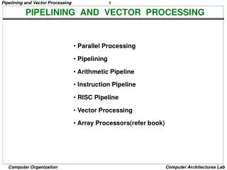
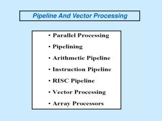
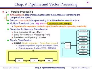
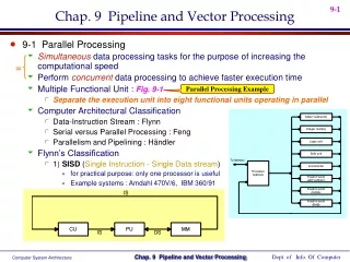
Parallel processing • A parallel processing system is able to perform concurrent data processing to achieve faster execution time • The system may have two or more ALUs and be able to execute two or more instructions at the same time • Goal is to increase the throughput– the amount of processing that can be accomplished during a given interval of time
Parallel processing classification Single instruction stream, single data stream – SISD Single instruction stream, multiple data stream – SIMD Multiple instruction stream, single data stream – MISD Multiple instruction stream, multiple data stream – MIMD
Single instruction stream, single data stream – SISD • Single control unit, single computer, and a memory unit • Instructions are executed sequentially. Parallel processing may be achieved by means of multiple functional units or by pipeline processing
Single instruction stream, multiple data stream – SIMD • Represents an organization that includes many processing units under the supervision of a common control unit. • Includes multiple processing units with a single control unit. All processors receive the same instruction, but operate on different data.
Multiple instruction stream, single data stream – MISD • Theoretical only • processors receive different instructions, but operate on the same data.
Multiple instruction stream, multiple data stream – MIMD • A computer system capable of processing several programs at the same time. • Most multiprocessor and multicomputer systems can be classified in this category
Pipelining: Laundry Example Small laundry has one washer, one dryer and one operator, it takes 90 minutes to finish one load: Washer takes 30 minutes Dryer takes 40 minutes “operator folding” takes 20 minutes A B C D
Sequential Laundry This operator scheduled his loads to be delivered to the laundry every 90 minutes which is the time required to finish one load. In other words he will not start a new task unless he is already done with the previous task The process is sequential. Sequential laundry takes 6 hours for 4 loads A B C D 6 PM Midnight 7 8 9 11 10 Time 30 40 20 30 40 20 30 40 20 30 40 20 T a s k O r d e r 90 min
Efficiently scheduled laundry: Pipelined LaundryOperator start work ASAP Another operator asks for the delivery of loads to the laundry every 40 minutes!?. Pipelined laundry takes 3.5 hours for 4 loads 30 40 40 40 40 20 A B C D 6 PM Midnight 7 8 9 11 10 Time 40 40 40 T a s k O r d e r
Pipelining Facts Multiple tasks operating simultaneously Pipelining doesn’t help latency of single task, it helps throughput of entire workload Pipeline rate limited by slowest pipeline stage Potential speedup = Number of pipe stages Unbalanced lengthsof pipe stages reduces speedup Time to “fill” pipeline and time to “drain” it reduces speedup 30 40 40 40 40 20 A B C D 6 PM 7 8 9 Time T a s k O r d e r The washer waits for the dryer for 10 minutes
9.2 Pipelining • Decomposes a sequential process into segments. • Divide the processor into segment processors each one is dedicated to a particular segment. • Each segment is executed in a dedicated segment-processor operates concurrently with all other segments. • Information flows through these multiple hardware segments.
k segments 9.2 Pipelining • Instruction execution is divided into k segments or stages • Instruction exits pipe stage k-1 and proceeds into pipe stage k • All pipe stages take the same amount of time; called one processor cycle • Length of the processor cycle is determined by the slowest pipe stage
SPEEDUP • Consider a k-segment pipeline operating on n data sets. (In the above example, k = 3 and n = 4.) • It takes k clock cycles to fill the pipeline and get the first result from the output of the pipeline. • After that the remaining (n - 1) results will come out at each clock cycle. • It therefore takes (k + n - 1) clock cycles to complete the task.
Example • A non-pipeline system takes 100ns to process a task; • the same task can be processed in a FIVE-segment pipeline into 20ns, each • Determine how much time does it required to finish 10 tasks?
SPEEDUP • If we execute the same task sequentially in a single processing unit, it takes (k * n) clock cycles. • The speedup gained by using the pipeline is:
Example • A non-pipeline system takes 100ns to process a task; • the same task can be processed in a FIVE-segment pipeline into 20ns, each • Determine the speedup ratio of the pipeline for 1000 tasks?
5-Stage Pipelining S1 1 2 3 4 5 6 7 8 9 S2 1 2 3 4 5 6 7 8 S3 1 2 3 4 5 6 7 S4 1 2 3 4 5 6 S5 1 2 3 4 5 S1 S2 S3 S4 S5 Fetch Instruction (FI) Decode Instruction (DI) Fetch Operand (FO) Execution Instruction (EI) Write Operand (WO) Time
Example Answer • Speedup Ratio for 1000 tasks: 100*1000 / (5 + 1000 -1)*20 = 4.98
Example • A non-pipeline system takes 100ns to process a task; • the same task can be processed in a six-segment pipeline with the time delay of each segment in the pipeline is as follows 20ns, 25ns, 30ns, 10ns, 15ns, and 30ns. • Determine the speedup ratio of the pipeline for 10, 100, and 1000 tasks. What is the maximum speedup that can be achieved?
Example Answer • Speedup Ratio for 10 tasks: 100*10 / (6+10-1)*30 • Speedup Ratio for 100 tasks: 100*100 / (6+100-1)*30 • Speedup Ratio for 1000 tasks: 100*1000 / (6+1000-1)*30 • Maximum Speedup: 100*N/ (6+N-1)*30 = 10/3
Some definitions • Pipeline: is an implementation technique where multiple instructions are overlapped in execution. • Pipeline stage: The computer pipeline is to divided instruction processing into stages. • Each stage completes a part of an instruction and loads a new part in parallel.
Some definitions Throughput of the instruction pipeline is determined by how often an instruction exits the pipeline. Pipelining does not decrease the time for individual instruction execution. Instead, it increases instruction throughput. Machine cycle . The time required to move an instruction one step further in the pipeline. The length of the machine cycle is determined by the time required for the slowest pipe stage.
Instruction pipeline versus sequential processing sequential processing Instruction pipeline
Instruction pipeline (Contd.) sequential processing is faster for few instructions
Instructions seperate • 1. Fetch the instruction • 2. Decode the instruction • 3. Fetch the operands from memory • 4. Execute the instruction • 5. Store the results in the proper place
5-Stage Pipelining S1 1 2 3 4 5 6 7 8 9 S2 1 2 3 4 5 6 7 8 S3 1 2 3 4 5 6 7 S4 1 2 3 4 5 6 S5 1 2 3 4 5 S1 S2 S3 S4 S5 Fetch Instruction (FI) Decode Instruction (DI) Fetch Operand (FO) Execution Instruction (EI) Write Operand (WO) Time
Five Stage Instruction Pipeline Fetch instruction Decode instruction Fetch operands Execute instructions Write result
Difficulties... If a complicated memory access occurs in stage 1, stage 2 will be delayed and the rest of the pipe is stalled. If there is a branch, if.. and jump, then some of the instructions that have already entered the pipeline should not be processed. We need to deal with these difficulties to keep the pipeline moving
Pipeline Hazards • There are situations, called hazards, that prevent the next instruction in the instruction stream from executing during its designated cycle • There are three classes of hazards • Structural hazard • Data hazard • Branch hazard
Pipeline Hazards • Structural hazard • Resource conflicts when the hardware cannot support all possible combination of instructions simultaneously • Data hazard • An instruction depends on the results of a previous instruction • Branch hazard • Instructions that change the PC
Structural hazard • Some pipeline processors have shared a single-memory pipeline for data and instructions
S1 1 2 3 4 5 6 7 8 9 S2 1 2 3 4 5 6 7 8 S3 1 2 3 4 5 6 7 S4 1 2 3 4 5 6 S5 1 2 3 4 5 Structural hazard Memory data fetch requires on FI and FO S1 S2 S3 S4 S5 Fetch Instruction (FI) Decode Instruction (DI) Fetch Operand (FO) Execution Instruction (EI) Write Operand (WO) Time
Structural hazard • To solve this hazard, we “stall” the pipeline until the resource is freed • A stall is commonly called pipeline bubble, since it floats through the pipeline taking space but carry no useful work
Structural hazard Fetch Instruction (FI) Decode Instruction (DI) Fetch Operand (FO) Execution Instruction (EI) Write Operand (WO) Time
Data hazard Example: ADD R1R2+R3 SUB R4R1-R5 AND R6R1 AND R7 OR R8R1 OR R9 XOR R10R1 XOR R11
Data hazard FO: fetch data value WO: store the executed value S1 S2 S3 S4 S5 Fetch Instruction (FI) Decode Instruction (DI) Fetch Operand (FO) Execution Instruction (EI) Write Operand (WO) Time
Data hazard • Delay load approach inserts a no-operation instruction to avoid the data conflict ADD R1R2+R3 No-op No-op SUB R4R1-R5 AND R6R1 AND R7 OR R8R1 OR R9 XOR R10R1 XOR R11
Data hazard • It can be further solved by a simple hardware technique called forwarding (also called bypassing or short-circuiting) • The insight in forwarding is that the result is not really needed by SUB until the ADD execute completely • If the forwarding hardware detects that the previous ALU operation has written the register corresponding to a source for the current ALU operation, control logic selects the results in ALU instead of from memory
Branch hazards • Branch hazards can cause a greater performance loss for pipelines • When a branch instruction is executed, it may or may not change the PC • If a branch changes the PC to its target address, it is a taken branch • Otherwise, it is untaken
Branch hazards • There are FOUR schemes to handle branch hazards • Freeze scheme • Predict-untaken scheme • Predict-taken scheme • Delayed branch
5-Stage Pipelining S1 1 2 3 4 5 6 7 8 9 S2 1 2 3 4 5 6 7 8 S3 1 2 3 4 5 6 7 S4 1 2 3 4 5 6 S5 1 2 3 4 5 Fetch Instruction (FI) Decode Instruction (DI) Fetch Operand (FO) Execution Instruction (EI) Write Operand (WO) Time
Branch Untaken (Freeze approach) • The simplest method of dealing with branches is to redo the fetch following a branch Fetch Instruction (FI) Decode Instruction (DI) Fetch Operand (FO) Execution Instruction (EI) Write Operand (WO)
Branch Taken (Freeze approach) • The simplest method of dealing with branches is to redo the fetch following a branch Fetch Instruction (FI) Decode Instruction (DI) Fetch Operand (FO) Execution Instruction (EI) Write Operand (WO)
Branch Taken (Freeze approach) • The simplest scheme to handle branches is to freeze the pipeline holding or deleting any instructions after the branch until the branch destination is known • The attractiveness of this solution lies primarily in its simplicity both for hardware and software
Branch Hazards(Predicted-untaken) • A higher performance, and only slightly more complex, scheme is to treat every branch as not taken • It is implemented by continuing to fetch instructions as if the branch were normal instruction • The pipeline looks the same if the branch is not taken • If the branch is taken, we need to redo the fetch instruction
Branch Untaken (Predicted-untaken) Fetch Instruction (FI) Decode Instruction (DI) Fetch Operand (FO) Execution Instruction (EI) Write Operand (WO) Time
Branch Taken (Predicted-untaken) Fetch Instruction (FI) Decode Instruction (DI) Fetch Operand (FO) Execution Instruction (EI) Write Operand (WO)