Download
1 / 14
150 likes | 647 Vues
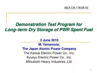
IAEA-CN-178/08-03. Demonstration Test Program for Long – term Dry Storage of PWR Spent Fuel. 2 June 2010 M. Yamamoto, The Japan Atomic Power Company The Kansai Electric Power Co., Inc. Kyusyu Electric Power Co., Inc. Mitsubishi Heavy Industries, Ltd. Contents . 1. Introduction

E N D
IAEA-CN-178/08-03 Demonstration Test Program for Long–term Dry Storage of PWR Spent Fuel 2 June 2010 M. Yamamoto, The Japan Atomic Power Company The Kansai Electric Power Co., Inc. Kyusyu Electric Power Co., Inc. Mitsubishi Heavy Industries, Ltd.
Contents • 1. Introduction 2. Demonstration Test Program • Test Overview and Process • Fuel Assemblies for Test • Outline of Test Container • Verification Method of Fuel Integrity • Confirmation during Storage Tests • 3. Designing of Test Container • Current Knowledge and Experience • Simulated Environment of Actual Casks • 4. Summary
1. Introduction • Mutsu interim spent fuel storage facility in Japan is preparing for the maximum 50-year storage of spent fuel in dry metal casks for both transportation and storage. • To reduce risk of radiation exposure to workers and waste materials, the facility has no hot cells, and the spent fuel will be confirmed for their integrity indirectly by monitoring casks during storage and transported after the storage without opening the cask lid. Lots of fuel cladding integrity investigations in Japan Lots of demonstrations & experiences in overseas Dry storage experiences of BWR fuel in Japan Long-term storage test for “fuel integrity” in domestic research facility to accumulate knowledge and experience on long-term integrity of PWR spent fuel during dry storage. To make assurance doubly sure on safety of transportation after storage.
2. Demonstration Test Program (1/5) Test Overview and Process Time Schedule of Demonstration Test of PWR Fuel Storage Planning Designing Safety analysis Licensing Manufacturing of test container Thermal test Preparation & Fuel inspection Loading to container (55GWd/t fuel) (48GWd/t fuel) 48GWd/t type fuel test 55 GWd/t type fuel test Gas sampling
2. Demonstration Test Program (2/5) Fuel Assemblies for Test • Up to two spent fuel assemblies (Type 48GWd/t and 55GWd/t ) will be stored. • 48GWd/t :Some of the fuel rods were used for PIE tests, and now it is stored in the pool of the hot laboratory in Tokaimura (NDC). • 55GWd/t : a proper spent fuel will be prepared in the future. Fuel assemblies Assumed for Tests *Fuel rods used in PIE are never used for long-term storage tests.
2. Demonstration Test Program (3/5)Outline of Test Container Outline Lid Outer thermal insulator* Inner thermal insulator Cross section Mid-body Inner container PWR spent fuel assemblies Basket spacer (Boron-Al) Neutron shield Basket (Stainless steel) Trunnion *Note: Outer thermal insulator installed at loading only 48GWd/t F/A is removed when 55GWd/t fuel assembly is added.
2. Demonstration Test Program (4/5)Verification Method of Fuel Integrity Loading to test container* • * The following inspections of sampled cover gas are to be carried out at the start of storage test after fuel loading; • – Kr-85 radioactivity analysis • – Gas composition analysis [ 48GWd/t fuel assembly] Start of Storage Test under Dry Condition Inspection of fuel before storage test – Visual inspection of fuel assembly 10 years Analysis and monitoring during storage test Loading to test container* [ 55GWd/t fuel assembly] Inspection of fuel before storage test – Kr-85 radioactivity analysis – Gas composition analysis – Monitoring of surface temperature of test container – Monitoring of containment boundary pressure of test container – Visual inspection of fuel assembly Increase of Kr-85 level End of Test Inspection of fuel after storage test Suspension of Test Investigation of cause Flow Diagram of Test Program – Visual inspection of fuel assembly
2. Demonstration Test Program (5/5)Confirmation during Storage Tests Sampling of cover gas in test container - Confirm detection of fuel leakage - Induction of cover gas into sampling pod - Scheduling every 5 years - Radioactive gas (Kr-85) analysis with a Ge detector - Gas components analysis with a mass spectrometer Temperature monitoring - Estimate temperature history of fuel rods - Installation of thermocouples on the outer surface in the middle area. - Calculation of the fuel rods temperature with a previously-verified assessment tool by thermal performance tests. Pressure monitoring - Confirm maintenance of containment of the test container - Monitoring of helium gas pressure at the lid boundary. - Installation of pressure gauges to a buffer tank leading to gap of double metal gaskets.
3. Designing of Test Container (1/4) Current Knowledge and Experience Evaluation of Degradation Events
3. Designing of Test Container (2/4)Simulated Environment of Actual Casks Chemical degradation • The test container is filled with helium gas having negative pressure as with actual dry cask cavity. • Vacuum drying operation is carried out before backfilling of helium gas. • Amount of moisture is confirmed. • Mechanical strength of cladding tubes shows saturation and ductility shows slow deterioration at low burn-up (around 5GWd/t). • Test fuel Burn-up is 42.8GWd/t. (Irradiation dose is 1021 to 1022n/cm2) • The test container is statically positioned in a vertical direction. Radiation degradation Mechanical degradation
Maximum temperature (°C) 230 210 1 3 55GWd/t fuel assembly 48GWd/t fuel assembly 2 0 10 Test Time (year) 3. Designing of Test Container (3/4) Simulated Environment of Actual Casks --- Temperature Thermal degradation • The maximum temperature of fuel cladding tubes during the storage test is set as around 230°C regarding to design value of actual casks. • Gradual decrease of fuel temperature is simulated considering to the condition of actual casks. Schematic drawing of Max. Temperature transition
3. Designing of Test Container (4/4)Simulated Environment of Actual Casks --- Temperature Heat load and max. temperature of cladding at initial test conditions • Thermal analyses were conducted for estimation of max. temperature of fuel claddings covered with He gas. • The obtained temperatures will meet the aimed temperature around 230°C or more. Thermal Analyses of Test Container (during loading of 48&55GWd/t fuel assemblies)
4. Summary • Some Japanese utilities are planning to conduct a long-term storage test for up to 60 years by placing PWR fuel assemblies in a test container simulating temperature and internal gas of actual casks to accumulate knowledge and experience on long-term integrity of PWR spent fuel assemblies during dry storage. • The storage test plans such as test methods and inspection items, and container design have been prepared. In the future, safety analyses, licensing and manufacturing of the test container are to be done, and the storage test of 48GWd/t fuel assembly will start in fiscal 2012. • Thermal design of the test container is important. Its temperature is controlled with thermal insulators and heat-transfer performance is confirmed by heat transfer tests at the completion of the container. • Others ----- Japan Nuclear Energy Safety Organization (JNES) plans to participate in this test from a regulator’s standpoint. We will discuss its details in the future.
Wireless Web data logger Server PC T1 P2 P1 T2 Controlled area Non–controlled area V6 V7 V8 V9 V4 V3 V10 V5 Buffer tank Inert gas inlet / outlet V2 V1 Lid part Supplemental OHPConfirmation of containment Schematic Drawing of Pressure Monitoring