Download
1 / 14
140 likes | 307 Vues
Oscillator Design Choices-Modification. What we decided on. Advantages: Already have circuit to work with Circuit already operates with a range of input voltages and produces range of output voltages, just need to modify ranges to meet specifications Very stable oscillator Disadvantages:

E N D
Oscillator Design Choices-Modification • What we decided on. • Advantages: • Already have circuit to work with • Circuit already operates with a range of input voltages and produces range of output voltages, just need to modify ranges to meet specifications • Very stable oscillator • Disadvantages: • Still need to change most of the resistor and capacitor values from the original circuit to fit new specifications.
Demodulator Design • Two main options: • Analog hardware demodulating circuit • Similar to Trans-Tek’s current design • Difficult to modify or tune • DSP-based demodulation • Novel design process • Easy to change or tune as need • Specified by Trans-Tek
Demodulator Design • Two main options: • Analog hardware demodulating circuit • Similar to Trans-Tek’s current design • Difficult to modify or tune • DSP-based demodulation • Novel design process • Easy to change or tune as need • Specified by Trans-Tek
Demodulator Design - External Reference Signal Microcontroller Remove DC Offset Readout Device DC Offset LVDT Output
Demodulator Design - Internal Receive reference & output signals ADC Determine amplitude ratio Output analog DC voltage (with offset) Calculate corresponding DC ouput Identify phase shift
PCB Design Flexible PCB VS Rigid PCB
PCB Design • RIGID • Cheaper • More reliable • Thickness can vary FLEXIBLE • Expensive (Up to 4 times as expensive) • Less Reliable • Circuit component connection issues • Space too small in LVDT housing to be useful
PCB Manufacturing • Software – EagleCad • Free download • Possible Vendors • OSH Park (Cheaper, Lower Quality, Slower Production) • 4PCB (more expensive, Better Quality, Faster Production)
LVDT and the PCB Notice the small dimensions of the aluminum tubing. The extra space a flexible PCB would give is so small it is negligible. LVDT – Linear Variable Differential Transformer
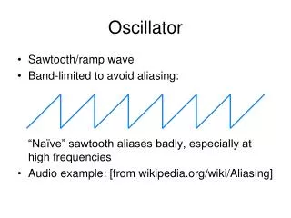
Goals • Use DSP preferred over hardware method. • Size Restraint: 0.700” DIAMETER TUBING, LENGTH T.B.D. • Series 1000 Oscillator Demodulator • Maintain accuracy and reliability • manipulate product dimensions • Oscillator: • maintain sinusoidal output, <1% harmonic distortion • Demodulator: • Maintain non-linearity <.03%
Progress • Oscillator • Parts ordered & received • Prototype currently being built • Demodulator • Software flow designed • Microcontroller ordered & received • PCB • Design software investigated
Budget • All required materials supplied by Trans-Tek • Need to buy: • PCB • Microcontroller/DSP • Component parts for protoboard and PCB • Total will amount to < $1000 • Amount spent to Date • Parts order for prototype: $95