DRAWINGS
DRAWINGS. ENG 205 CE-ME-MECE-MSE. DRAWING??. The ART or SKILL of making pictures, plans, etc. by using a pen or pencil. E ngineering D rawing (ED). A type of technical drawing used to define requirements for engineered items More than just the drawing of pictures


DRAWINGS
E N D
Presentation Transcript
DRAWINGS ENG 205 CE-ME-MECE-MSE
DRAWING?? The ART or SKILL of making pictures, plans, etc. by using a pen or pencil
EngineeringDrawing (ED) • A type of technical drawingused to define requirements for engineered items • More than just the drawing of pictures • A graphical language communicating ideas and information • Communicates all needed information from the engineer who designed a part to the workers who will make it.
EngineeringDrawing (ED) • ED & AD are both types of drawing • ED shares some traits with AD in that both create pictures. • The purpose of AD is to convey emotion or artistic sensitivity in some way (subjective impressions). • The purpose of ED is to convey information (objective facts).
EngineeringDrawing (ED) • Anyone can appreciate AD (even a viewer has his own unique appr.) • ED requires some training to understand (like any language) • But there is also a high degree of objective commonality in the interpretation (also like other languages). • ED has evolved into a language that is more precise than natural languages • It is closer to a programming language in its communication ability.
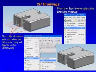
DRAWING TYPES & SCALES • In engineering, most design information is shown on drawings • They are produced on computer, using CAD (computer-aided design) systems. • CAD is pronounced as a word: /kæd/.
DRAWING TYPES & SCALES • Vocabulary item (CAD) Sample sentences • CAD systems which work in 3 dimensions will produce ‘drawing’ description files which actually describe the object being drawn, using 3D position co-ordinates. • The straightforward application of this figure implies that a drawing office could get rid of two-thirds of its draughtsmen if it installed a CAD system.
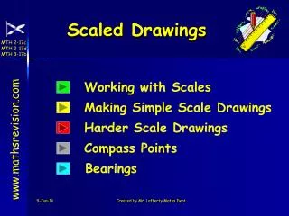
DRAWING TYPES & SCALES • A key factor on a drawing is the scale – that is, the size of items on the drawing in relation to their real size. • Scale: The relationship between the actual size of sth and its size on a map, diagram, or model that it represents • When all the items on a drawing are shown relative to their real size, the drawing is drawn to scale, and can be called a scaledrawing.
DRAWING TYPES & SCALES • An example of a scale is 1:10 (one to ten). At 1:10, an object with a length of 100 mm in real life would measure 10 mm on the drawing. • It was a scale drawing of a miniature microphone, perfectly reproduced, which was in reality no larger than a sugar cube. • Both plans are drawnto the same scale. • Our models are made to scale.
DRAWING TYPES & SCALES • Most engineering designs consist of a set of drawings (a number of related drawings): • General Arrangement (GA) drawings show whole devices or structures, using a small scale. This means objects on the drawing are small, relative to their real size (for example, a 1:100 drawing of an entire building).
DRAWING TYPES & SCALES • Detail drawings show parts in detail, using a large scale, such as 1:5 or 1:2. Small parts are sometimes shown in a detail as actual size (1:1), or can be enlarged to bigger than actual size (for example, 2:1).
DRAWING TYPES & SCALES • For electrical circuits, and pipe and duct networks, it is helpful to show designs in a simplified form. In this case, schematic drawings (often referred to as schematics) are used. An everyday example is the map of a train network. Schematic: In the form of a diagram that shows the main features or relationships but not the details. NOTE: When written, drawing is often abbreviated to dwg.
COMP. Qs (ask & answer the Qs. in pairs) 1) What kinds of drawings does Part A mention? Ans: General arrangement, detail, and schematic dwgs 2) Describe each drawing type, indicating the differences among them. Ans: GA dwgs show whole devices or building, using a small scale. On the other hand, detail dwgs show parts in detail, using a large scale. Schematic dwgs, different from the two, show designs such as electrical curcuits or duct (tube or pipe) networks in a very simplified form.
TYPES OF VIEWS ON DWG • Technicians are discussing different views shown on drawings (looking at components from above, from the side, etc.) as they search for the information they require. • We need a view from above showing the general arrangement of all of the roof panels –a plan of the whole area.
TYPES OF VIEWS ON DWG • Plan: A drawing of a building, room, or machine as it would be seen from above, showing the shape, size, and position of the wall, doors, and windows, etc. • A street plan (= a type of map of a town showing the roads) • An easy way of planning a new bathroom is to draw a 1:20 scale plan of the room on graph paper. • So the most helpful thing to do before you start shopping is to draw up a scale plan of the room.
TYPES OF VIEWS ON DWG • According to the list, there are elevations of all four sides of the machine on drawing 28. So one of those should show the front of the machine. • Elevation: One side of a building, or a drawing of this by an architect • This plan shows the front, side and rear (back) elevations of the new supermarket. • Only one of the four elevations of the building will be seen with the foreign office.
TYPES OF VIEWS ON DWG • The accompanying sketch gives an indication of the size of the front elevation of the ice-house. • The front/rear/side elevation of a house
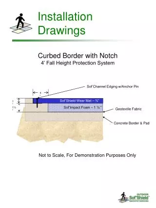
TYPES OF VIEWS ON DWG • There should be a section through the pipe, showing the valve inside, on drawing 36. • Section: a drawing or a diagram of sth as it would look if it were cut from top to bottom or from one side to the other. • The illustration shows a section through a leaf. • The architect drew the house in section.
TYPES OF VIEWS ON DWG • Figure 5.1 shows a section through this device. • The first diagram is a view of the shop from the street, and the second shows it in section.
TYPES OF VIEWS ON DWG • We need an exploded view of the mechanism, showing the components spaced out. • Exploded: showing the parts of sth separately but also showing how they are connected to each other • An exploded diagram of a plane/anengine • Natural history illustrations often included dissections, but it is striking to find in J. S. Miller's Crinoidea (1821) an exploded drawing of one of these ‘stone lilies’ or stalked starfish.
TYPES OF VIEWS ON DWG • An exploded view drawing is a diagram, picture or technical drawing of an object, that shows the relationship or order of assembly of various parts. • An exploded view shows an assembly's components spread out, but positioned to show how they fit together when assembled. • You create exploded views by selecting and dragging parts in the graphics area, creating one or more explode steps. In exploded views you can:
TYPES OF VIEWS ON DWG • Evenly space exploded stacks of components (hardware, washers, and so on). • Attach a new component to the existing explode steps of another component. This is useful if you add a new part to an assembly that already has an exploded view. • If a subassembly has an exploded view, reuse that view in a higher-level assembly. • Add explode lines to indicate component relationships. • While an assembly is exploded, you cannot add mates to the assembly.
TYPES OF VIEWS ON DWG • Oblique projection: shows an object with one of its faces at the front. The 3D shape of the object is shown by lines at 45 degrees from the horizontal. • A 45° plan oblique projection is sometimes referred to as an axonometric projection.
TYPES OF VIEWS ON DWG • Scholars have complained that mosaics are difficult to photograph even under good conditions: because of their size and situation, often only an obliqueview is possible. • While the realm of the mosaic begins at the entrance to the room, only an obliqueview of the entire composition is available from that vantage point.
TYPES OF VIEWS ON DWG • Isometric projection: shows an object with one of its corners at the front. The 3D shape of the object is shown by lines at 30 degrees from the horizontal. • It is an isometric view of a cube. • The isometric projection gives equal emphasis to all three dimensions, which are orientated at 120° intervals.
TYPES OF VIEWS ON DWG • The drawings for each component must contain an accurately dimensioned orthographic projection, and an isometricview of the parts. • Although they use rational elements, such as the cartographic technique of isometricprojection, maps like the Nouveau Paris Monumental willfully rearranged the orientation of the monuments they represented in order to display the most recognizable view of each.
EXERCISES & OVER TO YOU