WORKING DRAWINGS
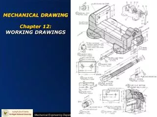
WORKING DRAWINGS. C H A P T E R T H I R T E E N. OBJECTIVES. 1. Define top-down, bottom-up, and middle-out design. 2. Discuss methods of constraining assemblies made using solid modeling and parametric modeling. 3. Identify the elements of a detail drawing.

WORKING DRAWINGS
E N D
Presentation Transcript
WORKING DRAWINGS C H A P T E R T H I R T E E N
OBJECTIVES 1. Define top-down, bottom-up, and middle-out design. 2. Discuss methods of constraining assemblies made using solid modeling and parametric modeling. 3. Identify the elements of a detail drawing. 4. List the parts of an assembly drawing. 5. List six types of assembly drawings. 6. List the role of the record strip and title block in the approval process. 7. Describe the process for revising drawings. 8. Describe the special requirements of a patent drawing.
Top-Down versus Bottom-Up Design Top down refers to starting the process of designing a product or system by considering the function of the entire system, then breaking that down into subassemblies or component groups based on their major functions Bottom up refers to a design process starting at the part level. Individual components are sized and designed, then the final assembly is built around the design of the parts Middle out refers to a combination of top-down and bottom-up design methods, where some parts are standardized and others are designed within the context of fitting into the design of the assembly. (Courtesy of Lunar.)
Constraining 3D Assembly Models With constraint-based modeling software, you use assembly constraints to create relationships between modeled parts. The first part added to the assembly becomes the parent part. Other parts are mated to this parent part to build up the assembly. Mating parts have features that should fit together. Assembly constraints available in the 3D modeling software let you align mating parts.
Assembly Drawings An assembly drawing shows the assembled machine or structure, with all detail parts in their functional positions or as an exploded view where you can relate the parts to their functional positions. There are different types of assembly drawings: 1. Design assemblies, or layouts. 2. General assemblies. 3. Detail assemblies. 4. Working drawing assemblies. 5. Outline or installation assemblies. 6. Inseparable assemblies (as in weldments, and others). 3D CAD Model for an Air Brake. (Courtesy of Dynojet Research, Inc.)
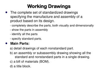
SUBASSEMBLIES A set of working drawings includes detail drawings of individual parts and the assembly drawing showing the assembled unit.
IDENTIFICATION Circled numbers called balloon numbers or ball tags are used to identify the parts in the assembly. Circles containing the part numbers are placed adjacent to the parts, with leaders terminated by arrowheads touching the parts. (Courtesy of Big Sky Laser.)
Multidetail Drawings When multiple detail drawings are shown on one sheet, label each part with identification similar to that used on way detail drawings Portion of a Drawing Showing Identification of Details with a Parts List
PARTS LISTS A parts list or bill of materials itemizes the parts of a structure shown on an assembly drawing. CAD software often allows you to generate the parts list automatically or somewhat automatically. (Courtesy of Solidworks Corporation.)
ASSEMBLY SECTIONS In assembly sections it is necessary not only to show the cut surfaces but also to distinguish between adjacent parts. Do this by drawing the section lines in opposing directions. Symbolic Section Lining
Other Assemblies After all detail drawings of a unit have been made, it may be necessary to make a check assembly, especially if a number of changes were made in the details. A working drawing assembly,is a combined detail and assembly drawing. An assembly made specifically to show how to install or erect a machine or structure is an installation assembly
Digital Drawing Transmittal Using electronic files saves trees, makes it quicker to distribute and store documents, and allows others to review documents from various applications. Electronic file formats such as Portable Document Format (PDF), originally developed by Adobe Systems in 1993, allow the originator to send a document that can be commented on without allowing the original document to be changed. A Portion of a PDF File Showing Redlined Markups. (Courtesy of Dynojet Research, Inc.)
Title and Record Strips The function of the title and record strip is to show, in an organized way, all necessary information not given directly on the drawing with its dimensions and notes. The following should generally be given in the title form: 1. Name of the object shown. 2. Name and address of manufacturer. 3. Name and address of the purchasing company, if any. 4. Signature of the person who made the drawing and date of completion. 5. Signature of the checker and date of completion. 6. Signature of the chief drafter, chief engineer, or other official, and the date of approval. 7. Scale of the drawing. 8. Number of the drawing. (Courtesy of Big Sky Laser, Inc.)
CHECKING DRAWINGS • The final checker should systematically review the drawing for any remaining errors. They should study the drawing with particular attention to: • 1. Soundness of design, with reference to function, strength, materials, economy, manufacturability, serviceability, ease of assembly and repair, lubrication, and so on. • 2. Choice of views, partial views, auxiliary views, sections, lettering, and so on. • 3. Dimensions, with special reference to repetition, ambiguity, legibility, omissions, errors, and finish marks. Special attention should be given to tolerances. • 4. Standard parts. In the interest of economy, as many parts as possible should be standard. • 5. Notes, with special reference to clear wording and legibility. • 6. Clearances. Moving parts should be checked in all possible positions to ensure freedom of movement. • 7. Title form information.
DRAWING REVISIONS The record of revisions should show the change, by whom, when, and why the change was made. An engineering change order (ECO) or engineering change request (ECR) is processed to approve and track changes to drawings once they have been released for production. Any changes or additions made to a drawing are tracked by a revision number. A symbol can be added to the drawing showing the item affected by the revision. “OBSOLETE” “SUPERSEDED BY” or “REPLACED BY” “SUPERSEDES” or “REPLACES,”
SIMPLIFYING DRAWINGS It makes sense to reduce drawing costs by using practices to simplify your drawings without losing clarity. • To simplify drawings: • 1. Use word descriptions when practical. • 2. Do not show unnecessary views. • 3. Use standard symbols such as Ø and standard abbreviations (see Appendix 2 when appropriate). • 4. Avoid elaborate, pictorial, or repetitive details. Use phantom • lines to avoid drawing repeated features. • 5. List rather than draw standard parts such as bolts, nuts, • keys, and pins. • 6. Omit unnecessary hidden lines. • 7. Use outline section lining in large areas to save time and • improve legibility. • 8. Omit unnecessary duplication of notes and lettering. • 9. Use symbolic representation for piping and thread. • 10. Use CAD libraries and standard parts when feasible for design • and drawings.
PATENT DRAWINGS Drawings for patent applications are pictorial and explanatory in nature; therefore they are not as detailed as working drawings for production purposes. Centerlines, hidden lines, dimension notes, and so forth, are omitted, since specific dimensions, tolerances, and notes are often not required to patent the general design or innovation. Patent Drawing Examples Although several examples are shown here, each drawing is shown on a separate sheet in the patent application.(Courtesy of US. Patent and Trademark Office.)