Working Drawings
Working Drawings. Chapter 12. Objectives. Define top down, bottom up, and middle out design Discuss methods of constraining assemblies made using solid modeling and parametric modeling Identify the elements of a detail drawing List the parts of an assembly drawing. Objectives (cont.).

Working Drawings
E N D
Presentation Transcript
Working Drawings Chapter 12
Objectives • Define top down, bottom up, and middle out design • Discuss methods of constraining assemblies made using solid modeling and parametric modeling • Identify the elements of a detail drawing • List the parts of an assembly drawing
Objectives (cont.) • List six types of assembly drawings • List the role of the record strip and title block in the approval process • Describe the process for revising drawings • Describe the special requirements of a patent drawing
Top Down Vs. Bottom Up Design • Top down refers to starting the process of design by: • Considering the function of the entire system • Breaking it down into subassemblies or components based on major functions • Each part is manufactured and assembled
Top Down Vs. Bottom Up Design • Bottom up design is helpful when the components are standardized parts: • The design process starts at the part level • Individual components are sized and designed • Final assembly is built around the design of the parts
Top Down Vs. Bottom Up Design • Middle out refers to a combination of top down and bottom up design: • Some parts are standardized • Other parts are designed within the context of fitting into the design of the assembly
Constraining 3D Assemblies • With constraint based modeling software, assembly constraints create relationships between modeled parts • The first part added to the assembly becomes the parent part • Other parts are mated to the parent part to build up the assembly
Constraining 3D Assemblies • Subassemblies are groups of components of a larger machine • Breaking products into subassemblies can make it easier to coordinate when different designers are working on portions of the same device
3D Layouts and Skeleton Assemblies • An assembly layout or skeleton assembly can be used to define locations of individual parts in an assembly • Parts are designed so they link to a skeleton framework in the assembly • The skeleton is a 3D drawing that defines major relationships in the assembly
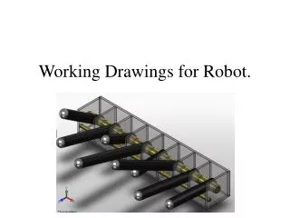
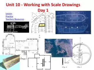
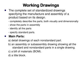
Working Drawings or Construction Drawings • Working drawings are a set of assembly and detail drawing • These drawings are given to contractors to perform work or manufacture individual parts • These drawings are legal documents
Assembly Drawings • Different type of assembly drawings include: • Design assemblies, or layouts • General assemblies • Detail assemblies • Working drawing assemblies • Outline or installation assemblies • Inseparable assemblies (weldments, etc.)
Assembly Drawings • Views should show how the parts fit together and suggest function of the unit • Hidden lines are typically not needed • Assembly drawings are usually not dimensioned
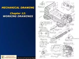
Detail Drawings • Detail drawings contain all of the necessary information to manufacture a part • Detail drawings are also called: • Piece part drawings • Part drawings
Multidetail Drawings • When multiple detail drawings are shown on one sheet, identify each part • Place the circles containing the part numbers adjacent to the parts
Parts Lists • A parts list or bill of materials (BOM) typically contains: • Part identification number (PIN) • Description of each part • Quantity required in the assembly • Abbreviations can be used to indicate quantities that are not known such as AR (as required) and EST (estimated quantity)
Assembly Sections • In assembly sections it is necessary to show cut surfaces and distinguish between adjacent parts • To accomplish this, section lines are drawn in opposing directions • In relatively thin parts, section lines should be left out or shown solid black • Bolts, nuts, keys, etc. are left unsectioned
Working Drawing Formats • Number of details per sheet: • Showing one detailed part per sheet is typically preferred • Machines or structures composed of few parts sometimes show all the details on one large sheet
Working Drawing Formats • Electronic file formats such as Portable Document Format (PDF) allow the originator to send a document that can be commented on without allowing the original document to be changed • Using electronic files also saves trees and makes distribution quicker
Working Drawing Formats • Title and record strips show all necessary information not given directly on the drawing with its dimensions and notes • The type of title used depends on the filing system, manufacturing processes, and requirements of the product
Working Drawing Formats • The title form typically includes: • Name of the object shown • Name and address of manufacturer • Name and address of purchasing company • Signature of person who made the drawing and date of completion • Signature of the checker and date of completion
Working Drawing Formats • Title form information (cont.) • Signature of the chief drafter, chief engineer, or other official, and the date of approval • Scale of the drawing • Number of the drawing
Checking Drawings • The final checker should review the drawing with particular attention to: • Soundness of design • Choice of views • Dimensions • Standard parts • Notes • Clearances • Title form information
Drawing Revisions • An accurate record of changes made to released drawings is tracked via a revision block • The record of revisions should show: • What change was made • By whom the change was made • When the change was made • Why the change was made
Simplifying Drawings • To simplify drawings: • Use word descriptions when practical • Do not show unnecessary views • Use standard symbols and abbreviations • Avoid elaborate, pictorial, or repetitive details • List rather than draw standard parts
Simplifying Drawings • Cont. • Omit unnecessary hidden lines • Use outline section lining in large areas • Omit unnecessary duplication of notes and lettering • Use symbolic representation for piping and thread • Use CAD libraries and standard parts when feasible
Patent Drawings • Patent applications must include line drawings • All patent drawings must be mechanically correct and constitute complete illustrations of every feature of the invention claimed • The U.S. Patent office has strict requirements for patent drawings