Working Drawings
Learn principles and techniques of detailed drawings production including shape description, size, notes, and more. Explore assembly drawings, subassemblies, parts lists, and title strips.

Working Drawings
E N D
Presentation Transcript
Working Drawings Competency: 00X.00 Explain and demonstrate working drawing principles and techniques. Objective: 00X.01 Explain the concepts and principles underlying the creation of detailed drawings. Engineering Drafting 3
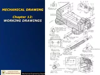
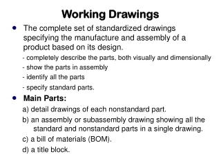
Detailed drawings • Detailed drawings are production drawings that show necessary views, dimensions, and notes required to make a part without the use of additional information. • Working drawings are made of an individual part. • Shape Description – necessary multiviews, sections, and auxiliaries • Size Description – size and location of features (dimensions) • Notes – specifications for material, finish, heat treating, etc.
Number of details per sheet • All details can be placed on individual sheets. • The sheets would then be numbered in drawing order or part importance. • When large or complicated mechanisms are represented, the details may be drawn on several sheets with several details to a sheet.
Number of details per sheet • If the structure is small or composed of few parts, all details can be drawn on one sheet. • Attention should first be given to spacing. • The same scale should be used for all details. • Each detail should be represented by the regular views, sections, or auxiliaries needed to describe the part clearly. • Must have all dimensions and notes. • Must identify all parts.
Identifying parts • The old method is to letter a title note under each detail, which would then be circled or underlined. • The new method is to give a parts list or bill of materials. • A bill of materials or parts list consists of an itemized list of the several parts of a structure shown on the drawing. The list can be given on a separate sheet.
Bill of materials or parts list • Lists part number, title, material, and quantity required. • May include pattern numbers, stock sizes, and weights. • The parts list is located above the title block reading upward or in the upper right corner reading downward. • Parts should be listed in general order of size or importance of details.
Title strip or title block • The title strip shows in an organized way all necessary information not shown on the drawing itself. The title strip should contain the following: • Name of the object represented. • Name and address of the manufacturer. • Name and address of the purchasing company, if any. • Signature of the drafter that made the drawing and the date of completion. • Signature of the checker and date of completion. • Signature of the chief drafter, chief engineer, or other official, and the date of approval. • Scale of the drawing. • Number of the drawing.
Drawing numbers • Every drawing should be numbered. • It is advisable to use simple serial numbers, but varies from industry to industry. • Avoid using drawing numbers to convey other information. • The drawing number is also the number of the part itself. • The drawing number is bold, ¼” high, and located in the lower right and upper left corner of the sheet.
Checking the drawing • When a drawing is completed it is turned over to the checker. It is checked for soundness of design, correct views, complete dimensioning, legibility, clearances, materials, standard parts, and title block information.
Change records • A change strip of revision strip is included at some convenient place on the drawing. • In the change strip, the change is briefly described, initialed, and dated. • The change is labeled on the drawing usually by an encircled letter.
Assembly drawings • Assembly drawings guide workers in assembling parts properly and for general reference throughout the shops. • Assembly drawings show the assembled machine or structure, with all detail parts in their functional positions.
Selecting views for an assembly • In selecting views for an assembly drawing, the drafter must keep in mind the purpose of the drawing, which is to show how the parts fit together and to suggest the function of the entire unit. • The assembly should not describe the shapes of individual parts. • The views selected should be the minimum views or partial views that will show how the parts fit together.
Subassemblies • A subassembly is used with large or complicated machines when it is not possible to show all parts in one assembly and a separate drawing is needed.
Title strips for assemblies • Title strips are the same for an assembly drawing as a detail drawing except for the addition of the word assembly in the title.
Parts lists • A parts list may be placed on a separate sheet or in any convenient open corner on the drawing. It is preferred to be read up from the title block or down from the upper right corner • The parts list includes the part number, name, material, and number of pieces required. • Each part is identified on the drawing by lettering the part numbers in .438 or .500 diameter circles near the assembly, and drawing leaders to each part where it is clearly shown. • The circles should be arranged in groups and in vertical or horizontal rows.
Assembly sections • In an assembly drawing where several adjacent parts are sectioned, it is necessary to draw the section lines in different directions to distinguish the pieces clearly. • The first large area is section-lined at 45o . • The next large area is then section-lined at 45o in the opposite direction. • Additional areas are section-lined at 30o or 60o with horizontal. • If necessary, to make any area contrast with the others, any other angle may be used.
Assembly sections • Section lines do not meet at the visible lines separating the areas. • For small areas the lines are drawn closer together. • In sectioning very thin parts, when there is not enough space for section-lining, the sectioned parts may be shown solid. • It is customary not to section parts that would make the drawing less clear, such as bolts, nuts, shafts, keys, ribs, gear teeth, spokes, screws, nails, ball and roller bearings, and pins.
Design assemblies or layouts • One of the initial drawings created by the designer, usually drawn to full scale to enable the designer to visualize the part more clearly. • Includes the views necessary to show the size and shape of each part of the mechanism, but dimensions are omitted.
Outline or installation assembly • The purpose is to give general information regarding the character and size of the unit and how it fits in its environment. • In an outline assembly there is little or no section lining. • Only the principal overall and center to center distances needed to clarify questions of installation are given.
Working drawing assembly • A working drawing assembly combines detail and assembly drawings giving complete dimensions and notes for all parts. • Used in place of separate detail and assembly drawings for simple parts.
General assembly • Shows how the part fits together and how the assembly functions. • Chief use is in the assembly shop where all finished parts are received and put together. • Views shown may be regular, sections, auxiliary, and partial. • No dimensions are usually given on a general assembly.