Download
1 / 92
960 likes | 1.25k Vues
Cirrus LSA Wing Design. Team Lead: David Gustafson Tyler Hawkins Nick Brown Bryce Holmgren. Project Goals. Utilize Edge Bonding Try New Light Weight Materials Incorporate Spin Resistance Total Weight Constraint < 170 lbs for entire wing. Obstacles.

E N D
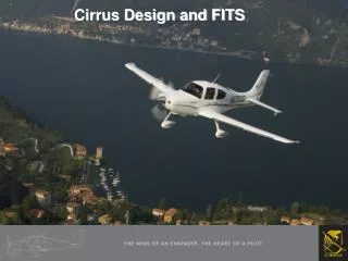
Cirrus LSA Wing Design Team Lead: David Gustafson Tyler Hawkins Nick Brown Bryce Holmgren
Project Goals • Utilize Edge Bonding • Try New Light Weight Materials • Incorporate Spin Resistance • Total Weight Constraint • < 170 lbs for entire wing
Obstacles • Edge Bonding vs. Required Strength and Existing Practice • New Materials • Cost • Performance • Spin Resistance vs. Manufacturing Simplicity • All of These vs. Weight and Performance
Areas of Design and Analysis • Loads Analysis • Aerodynamic Design • Materials Research and Testing • Structural Design
Cirrus Wing Aerodynamics and Control Bryce Holmgren
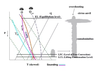
AerodynamicsDesign Constraints Light Sport Aircraft Requirements • Maximum Gross Weight: 1,320lbs • Maximum Stall Speed: 45 knots • Required Lift Coefficient to Meet Requirements: >1.60 Other Considerations • Spin Resistant Design • Enhanced Stall Performance
Aerodynamics Analysis Tools – XFLR5 • Developed by MIT • Contains Airfoil Generation Tool Called Xfoil • Recommended by Cirrus for Preliminary Design Analysis
Aerodynamics Initial Wing Design Parameters • Wing Span: 30 ft • Wing Area: 125 square ft Airfoil Database – University of Illinois at Urbana-Champaign
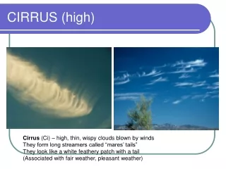
Aerodynamics Final Airfoil - NASA/Langley LS(1)-0417mod (also known as the GA(W)-1 airfoil)
Aerodynamics Drooped Leading Edge • Enhanced Spin Resistance
AerodynamicsWing Model in XFLR Plane weight of 1500 lbs and at 44 knots Lift Coefficient of 1.64 at 17˚ angle of attack
Aerodynamics Improvements • Less Aggressive Camber • Different Tip Airfoil
Controls Flaps • Fowler Flaps • Area: 24.4 ft^2 Ailerons • Differential Ailerons • Area: 12 ft^2
Cirrus Wing Materials Nick Brown
LSA FAA definition • Max gross takeoff weight = 1320 lbs • Max stall speed = 45 knots • Maximum speed in level flight = 120 knots
ASTM F 2245-07 guidelines • Limit load factors • Ultimate load factor of safety = 1.5 • Special ultimate S.F.s for hinges, bearings, pins, control components • Flight conditions • Design speeds
Design speeds • 45 knots = Stall speed (LSA) • 99.6 knots= Minimum maneuvering Speed • 108 knots = Minimum cruise • 120 knots = Maximum cruise (LSA) • 160 knots = Dive speed
Flight envelope VA VC,max VD Vs
Total Loads • Level flight 1320 lbs • Design Limit load = 5280 lbs • Ultimate load = 7920 lbs (for 3 seconds)
XFLR5 • Simulations • Various A.O.A. and Reynolds numbers • Wing panels • Data (spreadsheet) • Aerodynamic coefficients • Lift, drag, and moment forces
Shear and bending • Integrate ultimate load equations • From 0(root) to 8ft (airfoil switch) • F = -5.2139x + 318.37 • From 8ft to tip (15ft) • F = -3.255x2 +54.497x + 42.791
Torsion/control loads • 75% positive maneuvering load, plus torsion from max aileron displacement • Gust loads at VF with flaps extended (7.5 m/s)
Gusts • Symmetric vertical gusts (up and down) • 15 m/s at VC • 7.5 m/s at VD
Cirrus Wing Composite Panels & Adhesives David Gustafson
Composite Panels • Panels are fiberglass on both sides with a core in the middle consisting of either foam or a honeycomb structure
Final Core Material • HT Diab 61 - Wing Skins • Ability to lay up curves of Airfoils • Cheapest that met criteria of foams • Aramid Core - Spar, Aft Spar, Rib • Light Weight • Cheapest per Pound
Adhesive Options • DP 420 • 3M, Two Part Epoxy • From 3M Epoxy Comparison
Adhesive Options (Cont.) • PTM & W: • ES6292 Lightweight Tough Epoxy Adhesive • Two Part Epoxy • Designed for use in the structural assemblies involving composites • Already used by Cirrus Design Center
Adhesive Testing • Objectives: • Test Max Adhesive Loads • Need to make sure adhesives aren’t effected by surfaces • Test surface preparation techniques
Adhesive Testing (Cont.) • Materials Tested: • Adhesives: • PTM & W ES6292 • 3M DP 420 • Composites: • Aramid Core with Fiberglass Skin • HT Diab Foam Core with Tencate Fiberglass
Adhesive Testing (Cont.) • Tensile Test: • Load Bonds in Tension • Measure Load at Fracture • Calculate Lbs/In. Bond Strength • Test Equipment: • Constant Strain Load Cell • Measures Load and displacement
Adhesive Testing (Cont.) • Tensile Load Justification: • Jaws: • 2° freedom on both directions • Top & Bottom • All samples were applied within 1 degree of perpendicular • Therefore: Tension loads were perpendicular to bond
Adhesive Testing (Cont.) • Surface Preparation: • All surfaces were lightly sanded to rough up surface • All surfaces were cleaned with to remove
Adhesive Testing (Cont.) • Results: • Bond Strength per Inch of Bond (Lbs/In) • PTM & W ES6292= 81.7 ± 4.1 Lbs/In • 3M DP 420=87.1 ± 4.4 Lbs/In • Uncertainty Estimated at 5%
Adhesive Testing (Cont.) • Conclusions: • Adhesives were comparable in Strength per Inch • Both Adhesives meet strength requirements for wing • PTM & W ES6292 Adhesive is better because of lower cost
Adhesive Testing (Cont.) • Errors: • Improper preparation: • Issue: Samples broke at surface • Resolution: Better Surface Preparation • Sanding (possibly Sand Blasting) • Better Removal of oils from surface • Effect: • Bonds Broke Prematurely • With Better Preparation Bonds could hold more Weight
Adhesive Testing (Cont.) • Test Equipment: • Issue: Jaws Slipping • Resolution: Better Transition from Material to Jaw • Adhere Aluminum Tab into Composite • External Clamp System with Aluminum Tab for Jaw • Allow Material to be secured by clamp and Jaw to attach to Aluminum Tab • Effect: • Load might be underestimated. • Result: Bond Strength could be higher than reported
Adhesive Testing (Cont.) • Further Testing: • Shear Test Side View:
Adhesive Testing (Cont.) • Shear Test Top View: (Load Pulling out from picture)
Adhesive Testing (Cont.) • Shear Test:
Cirrus Wing Structures Tyler Hawkins
Structure • Goals • Light Weight • < 170 lbs. in total • Handle All Loads with Extra Safety Factor • Maintain Aerodynamic Shape • Attach to Fuselage Structure