Download

1 / 53
530 likes | 686 Vues
Beam Loss Monitoring for LHC Machine Protection. Eva Barbara Holzer for the BLM team CERN, Geneva, Switzerland TIPP 2011 June10, 2011 Chicago, USA

E N D
Beam Loss Monitoring for LHC Machine Protection Eva Barbara Holzer for the BLM team CERN, Geneva, Switzerland TIPP 2011 June10, 2011 Chicago, USA Bernd Dehning, Ewald Effinger, Jonathan Emery, Viatcheslav Grishin, Csaba Hajdu, Stephen Jackson, Christoph Kurfuerst, Aurelien Marsili, Marek Misiowiec, Eduardo Nebot Del Busto, Annika Nordt, Chris Roderick, Mariusz Sapinski, Christos Zamantzas
Content • Status of the LHC • The BLM system • Operational experience • Fast (ms-time-scale) losses, UFO: Unidentified Falling Object • BLMs and Collimation – Examples • Summary
LHC Layout CMS RF Beam Dump MomentumCollimation Betatron Collimation ALICE SPS LHCb Injection Beam 1 Injection Beam 2 ATLAS
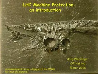
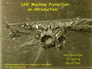
Stored Energy Challenge • Failure in protection loss of complete LHC is possible • Magnet quench hours of downtime • Magnet damage months of downtime, $ 1 million SPS incident in June 2008 400 GeV beam with 2 MJ (J. Wenninger, CERN-BE-2009-003-OP) ≈10cm
Machine Protection System Several 10.000 channels from ≈ 250 user input connections
Machine Protection System 4000 Beam Loss Monitors
2010 and 2011 beam aborts above injection energy BLMs: 23% of the protection dumps
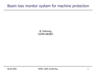
Beam Loss Measurement System Layout • Main purpose: prevent damage and quench • 3600 Ionization chambers (IC) interlock (97%) and observation • 300 Secondary emission monitors (SEM) for observation
Beam Abort Thresholds • 12 integration intervals: 40μs to 84s (32 energy levels) • Each monitor (connected to interlock system BIS) aborts beam: • One of 12 integration intervals over threshold • Internal test failed • Local protection strategy • Typically: thresholds set in conservative way at the start-up of LHC
Detector Tunnel electronics Surface electronics Combiner Functional tests before installation Barcode check Current source test Radioactive source test HV modulation test Beam inhibit lines tests Threshold table data base comparison Offset to check connectivity (10 pAtest) Double optical line comparison System component identity check Inspection frequency: ReceptionInstallation and yearly maintenanceBefore (each) fillParallel with beam Regular Validation Tests PhD thesis Gianluca Guaglio Threshold table beam inhibit check
System Validation Tests — Examples • Extensive firmware test before new release: all operational functionalities including all issues of previous versions • `Vertical slice test’ • Test system installed at LHC point – real environment • Complete chain: IC to beam interlock output • among others: front end emulator • Exhaustive threshold triggering • Optical link reception and status tests • Response to predefined input patterns (linearity etc.)
Commissioning with Beam • Machine protection functionalities phased in: • Provide required protection level for each commissioning stage depending on damage potential of the beam • Not compromise the availability • Activation (‘unmasking’) of individual monitors in stages (‘masked’: abort request ignored, if ‘set-up beam’ flag true) • System validation tests switched on in stages
System Modifications since January 2010 • Increase upper end of dynamic range • Very high losses (>23 Gy/s) on IC saturate electronics while SEM mostly below noise • IC (measurement only) – RC readout delay filter (factor 180) • New less sensitive IC • Non-local losses - showers from upstream losses: Thresholds defined according to operational scenario - Deviate from local protection scheme on a few monitors • Collimation regions • Injection regions (injection energy thresholds) • Cold magnet thresholds changed (start-up 2011) according to quench tests and experience with measured losses
BLM Threshold Change Cold Magnets 2011 • Quench Tests at Injection • MB quenches at injection thresholds increased (factor 1.5) according to measurements Quench Test Circulating Beams thresholds 2-3 times too high UFOs quench level at least 2.4 times higher on MQML Wire Scanner Test quench level at least 16 times higher on MQY and MBRB
Dependability (Reliability, Availability and Safety) • SIL (Safety Integrity Level) approach tosystem design (Gianluca Guaglio) • Damage risk: • Simulation assumed 100 dangerous losses per year, which can only be detected by one BLM 80 BLM emergency dumps in 1.5 years observed protection redundancy (several local monitors and aperture limits see beam loss)
Dependability (Reliability, Availability and Safety) • Thresholds: • No avoidable quench (all beam induced quenches with injected beam) • All exceptionally high losses caught • 1 issue detected: power cable cut at surface – detected by internal monitoring, no immediate action on beam permit (only during regular system test) added to software interlock immediately and later to hardware interlock • Hardware failures: • Mostly, onset of system degradation detected by regular offline checks before malfunction • Firmware updates: 3 in 2010; 2 (+1 pending) in 2011 extensive testing (‘vertical slice’ etc.)!
Beam Aborts due to UFO’s • Stepwise increase of BLM thresholds at the end of 2010 run • New BLM thresholds on cold magnets for 2011 start-up • 11 UFO dumps 27 May – 8 June • Always detected by > 6 local monitors (at least 3 close to threshold) and at all aperture limits (collimators) redundancy • most UFOs far from dump threshold 2010
UFO Duration 2010 and 2011 E. Nebot Protons / beam
Intensity Dependence – UFO Rate 2010 E. Nebot • Rate increases with intensity; prediction from 2010 data:2000 Bunches ≈ 5.2 events/hour
Spatial UFO Distribution T. Baer 3.5 TeV628 candidate UFOs. Signal RS05 > 5∙10-4Gy/s. 450 GeV137 candidate UFOs. Signal RS05 > 5∙10-4Gy/s. Distributed around the ring 38 UFO Candidates at Injection Kicker Beam 2 UFOs mainly at Injection Kickers
Injection Kicker UFOs During Scrubbing • Injection Kicker UFOs during scrubbing run: Loss spikes during first few minutes after an injection Injection Losses B2 Injection Kicker Intensity B2 UFO’s 2 hours
BLMs and Collimation - Examples Collimator set-up Collimation performance verification
1.2 m beam Collimation System • Three stage collimation system (≈100 collimators and absorbers) • Primary: deflection • Secondary: absorbtion • Tertiary: tripletprotection • Special dump and injection protection collimators
G. Valentino D. Wollmann Collimator Set-Up Find center and relative size of beam at collimator location using BLM signal Set-up procedure: • Define beam edge by primary collimator • Find beam edge with secondary collimator and center jaws • Re-center primary collimator Define beam center at collimator positions and the relative beta • Open collimators to reference position 1. Secondary Collimator Primary Collimator BLM BLM Beam 2. Secondary Collimator Primary Collimator BLM BLM Beam
G. Valentino D. Wollmann Semi-Automatic Setup Procedure • Automatic step-wise movement of collimator jaws (user defined 5 – 100 µm steps) • Stop after reaching user defined BLM threshold (1 Hz logging data) • Reduction in set-up time up to a factor of 6 with semi-automatic procedure using the BLM (2011) as compared to manual procedure in 2010 • Plan for 2012: use 30 Hz BLM data (special buffer for collimators) to further reduce set-up time BLM Signal Threshold Jaw Positions Time
Machine Study I R.W. Assmann et al. Settings in nominal beam sigma at 3.5 TeV
Observed Losses (Normalized to Primary Collimator) R.W. Assmann et al. ‘loss map’: collimation performance verification 99.995 %
(In-) Efficiency Reached (Coll SC Magnet) R.W. Assmann et al. 99.960 % worse 99.995 % MD better
Machine Study II R.W. Assmann et al. • Plan maximizing the loss rates on primary collimator • either: up to design loss rate of 500 kW • or: until quench in the dispersion suppressor • Loss by crossing 1/3 resonance • 16 bunches, 3.5 TeV
Machine Study II R.W. Assmann et al. • Plan maximizing the loss rates on primary collimator • either: up to design loss rate of 500 kW • or: until quench in the dispersion suppressor • Loss by crossing 1/3 resonance • 16 bunches, 3.5 TeV Loss rate: 9e11 p/s @ 3.5 TeV 505 kW
Leakage into Cold Magnets R.W. Assmann et al. 3.5 TeV operational collimator settings (not best possible) No quench – consistent with BLM readings (64% of assumed quench level)
Decomposition of Losses PhD A. Marsili Loss patterns at Betatron Collimation
Decomposition Results PhD A. Marsili Work in progress Physics beam, 1 point per second
Summary • No evidence of a single beam loss event been missed • No avoidable quench passed BLM protection • 1 protection hole found and closed in the design of the tests • Fewer hardware failures than expected
Summary • No avoidable quench passed BLM protection • No dumps on noise • Initial threshold settings conservative, still appropriate for first year (except non-local losses)
Noise • Important for availability (false dumps) and dynamic range • 1 monitor disabled for short term - no dump on noise • Main source of noise: long cables (up to 800 m in straight section) • Aim: factor 10 between noise and threshold • Thresholds decrease with increasing energy noise reduction before 7 TeV • Single pair shielded cables, noise reduction: > factor 5 • Development of kGy radiation hard readout to avoid long cables
Dump on 01.05.2011 • Dump of BLMQI.04L2.B1E20_MQY on RS 3, 4 and 5
Dump on 01.05.2011 • From fit of PM data • (BLMEI.05L2.B1E10_MKI.D5L2.B1): • Amplitude: 0.63 Gy/s • Width: 0.29 ms
On average: 10 candidates/hour 2011 Rate of UFO Candidates T. Baer 480 b 72 bpi 336 b 72 bpi 336 b 72 bpi 480 b 36 bpi 624 b 72 bpi 480 b 36 bpi 768 b 72 bpi UFO Candidates / hour for 3.5 TeV Fill Number
Accuracy of Thresholds • All quenches so far on dipoles with injected beam. • 2 quenches in 2008: signals in BLMs could be reproduced by GEANT4 simulations to a factor of 1.5 thresholds raised by 50% in 2009 • Analysis of second quench • LHC Project Note 422
Regular Tests – HV Modulation Test • Decision of pass or fail in surface electronics FPGA (combiner) • Duration: 7 minutes Tests: • Comparison between data base and backend electronics (MCS) • Internal beam permit line test (VME crate) • Connectivity check (modulation of chamber HV voltage supply) amplitude an phase limit checks BLECS Modulate High Voltage Monitors in tunnel BLM acquisition chain Capacitor missingor disconnected BLM Diagnostic application Amplitude [RS09_Bit] Normal behavior Digital signal processing and decisioninside the FPGA Samples ( from 1Hz logging => 15Hz )
System Validation Tests — Examples • Extensive firmware test (including all issues of previous versions) – before new release: all operational functionalities • `Vertical slice test’ • Test system installed at LHC point – real environment • Complete chain: IC to beam interlock output • among others: front end emulator • Exhaustive threshold triggering • Optical link reception and status tests • Response to predefined input patterns (linearity etc.) • Performance tests with beam include: • Beam abort with injection losses on closed collimator • BLM reaction time (injection kicker to break of beam permit): 100 – 130 μs.