Telecom WIA Training
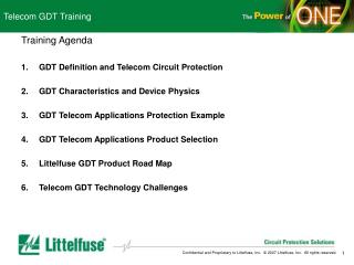
Telecom WIA Training. Training Agenda Fuse Definition and Telecom Circuit Protection Needs WIA Fuse Characteristics and Device Physics WIA Fuse Telecom Application Protection Examples WIA Fuse Telecom Application Product Selection Littelfuse WIA Fuse Product Road Map

Telecom WIA Training
E N D
Presentation Transcript
Telecom WIA Training Training Agenda • Fuse Definition and Telecom Circuit Protection Needs • WIA Fuse Characteristics and Device Physics • WIA Fuse Telecom Application Protection Examples • WIA Fuse Telecom Application Product Selection • Littelfuse WIA Fuse Product Road Map • Telecom WIA Fuse Technology Challenges
Telecom WIA Training Section 1 Fuse Definition and Telecom Circuit Protection Needs • Fuse Definition • A fuse is a calibrated, intentionally weak link in an electrical circuit that provides over-current protection. • Circuit Protection Needs in the Telecom Segment • Lightning • ESD • Inductive • Short Circuit/Power-Cross • Fuse Technology for Telecom Overcurrent Circuit Protection • Elimination of series line resistance enabling longer loop lengths • Precise longitudinal balance allowing better transmission quality • Typical Telecom Test Standards • ITU K.20 K.21 • Bellcore GR-1089 • UL 60950 • Typical Fuse Test Standards • IEC 60127 • UL 248 • MITI
Fuse Definition and Telecom Circuit Protection Fuse Definition • A fuse is a calibrated, intentionally weak link in an electrical circuit. • Fuses function by reacting to the heat generated from excessive current flow. Once the fuses I2t rating is exceeded, the center conductor opens. • A fuse is used to prevent fires and overheating when something goes wrong with electrical equipment. This can be the result of an accident, such as unintentional contact between power and the telephone line, an improper connection/installation, poor maintenance work, or a vandalism. • A fuse is intended to operate before a catastrophic event occurs and can create a safety hazard. Electrical components such as capacitors, transformers, resistors, etc., can fail due to a manufacturing defect or old age, and could draw an excessive amount of current and catch fire. • A fuse does not prevent a fault from occurring, but will operate quickly to prevent further damage occurring or the equipment becoming a safety hazard. The fuse can also limit the extent of the damage to a small portion of the equipment making repairs less costly • IEC, UL, MITI, and CCC standards all provide definitions and requirements for fuses. For example, IEC-127 gives specific dimensional requirements and also specifying a series of fuse tests.
Fuse Definition and Telecom Circuit Protection Circuit Protection Needs in Telecom Systems • Thunderstorms around the world deliver 8 million lightning flashes every day. Peak current in lightning discharges range from a few KA to many hundreds of KA. Induced currents from indirect strikes range from 10A to 20KA. • ESD results from the build up of electrical charge, when two non-conductive materials are brought together then separated. The potential between a human body & an object can exceed 35,000 volts. An ESD event can occur to the telecom system or portable devices through human contact and usage of the telecom devices. • Inductive Load Switching is caused when an inductive load is interrupted. It occurs in factory/industrial environments where motors and relays (inductive loads) are turned on and off. • Short Circuit or Power Cross events can occur due to human error (such cutting a phone and power line simultaneously during construction) or natural disaster such as hurricane, thunderstorm. • One or a combination of the above threats can have obvious adverse effects on semiconductor/IC devices, electro-mechanical contacts, wiring insulation, etc., to cause interruption of telecom equipment operation, telephone service, and even fire.
Fuse Definition and Telecom Circuit Protection Fuse Technology for Telecom Overcurrent Circuit Protection Telecom equipment should be protected from overcurrnent conditions using either PTCs, fuses, power/line feed resistors, or flameproof resistors. • A Fuse is a series element placed in front of the overvoltage protector on either Tip or Ring for metallic applications and on both Tip and Ring for longitudinal applications. Due to their stability, fuses are one of the most popular solutions for meeting AC power cross requirements for telecommunications equipment. • Littelfuse Telecom WIA Fuses are designed to only interrupt a circuit when extreme fault conditions exist and, when coordinated properly with an overvoltage protector, offer a very competitive and effective solution for transient immunity needs. Advantages include: • Elimination of series line resistance enabling longer loop lengths • Precise longitudinal balance allowing better transmission quality • Robust surge performance which eliminates costly down time due to nuisance blows • Greater surge ratings than resettable devices, ensuring regulatory compliance • Non-degenerative performance • Telecommunication equipment best suited for a fuse is equipment that requires surface mount technology (and is thus sensitive to transients), accurate longitudinal balance, and regulatory compliance without the use of additional series line impedance.
Fuse Definition and Telecom Circuit Protection Subscriber Premises Central Office Outside Plant MDF SLIC Switch DDF To PSTN Trunk Line (T1, T3, HDSL, etc.) Overhead Cable Customer Premise Equipment (CPE) Network Interface Device (NID) Street Cabinet & SLIC (if on DLC system) Underground Cable YD/T993 ITU-T K.21 FCC P 68 UL 60950 UL 497 YD/T950 ITU-T K.20 GR 1089 UL 60950 YD/T993 ITU-T K.21 FCC P 68 UL 60950 YD/T1082 ITU-T K.45 GR 1089 UL 60950 UL 497 YD/T 694 or YD/T 940 ITU-T K.28 GR 1089 UL 60950 UL 497 Telecom System Test Standards
Fuse Definition and Telecom Circuit Protection WIA Fuse Standards • IEC 127 Specification • 5 BASIC GATES • HOLD 1.5In 60 MINUTES • OPEN 2.1In 30 MINUTES (2MINS T ) • OPEN 2.75In VARIES T/F HBC/LBC • OPEN 4.0In VARIES T/F HBC/LBC • OPEN 10In F<20mS T>20mS • BREAKING CAPACITY 250V ac • HBC HIGH BREAKING CAPACITY 1500A • LBC LOW BREAKING CAPACITY 35A or 10In • EBC ENHANCED BREAKING CAPACITY 150A • FUSING FACTORS • 1.7 OF FUSE RATING • UL 248 Specification • 3 BASIC GATES • HOLD 110% 4 HOURS * (UL198G) • OPEN 135% 1 HOUR • OPEN 200% 2 MINUTES • INTERRUPTING RATING • 125V 10kA • 250V 35A to 1500A • FUSING FACTORS • 1.2/1.3 OF FUSE RATING • MITI Specification • 3 BASIC GATES • HOLD 130% 60 MINUTES • OPEN 160% 60 MINUTES • OPEN 200% 2 MINUTES • INTERRUPTING RATING • 125V 500A • 250V 100A • FUSING FACTORS • 1.5 OF FUSE RATING
Telecom WIA Training Section 2 WIA Fuse Characteristics and Device Physics • Basic Fuse Characteristics • Electrical Characteristics • TC Curve • I2t • Fast Acting and Slo Blo Fuses • Maximum Ratings (Breaking Capacity) • Fuse Voltage Rating • Pulse Withstanding Curve • Thermal Characteristics • De-rating • Fuse Construction and How it Affects Fuse Characteristics • Fuse Construction • Fuse Physics and Equations • Fuse I2t and Arcing • Fuse Element: Slow-blow vs. Fast Acting • Fuse Body Strength and Breaking Capacity
WIA Fuse Characteristics and Device Physics Basic Fuse Electrical Characteristics • TC Curve • Defines the fuse opening time • Illustrates phase change of the fuse element state • Directly denotes the fuse rating • Difference in Slow Blow vs. Fast Acting • Typical overload 200% to 800% for electronics fuse • Above 1000% considered to be short circuit • I2t 1. Adiabatic Process: No heat transfer to surrounding. All energy concentrated in a specific area for a split second. 2. Measure of the energy required to open a fuse when subjected to an adiabatic current pulse. 3. Due to adiabatic current pulses, the fusing element is stressed both thermally and mechanically. Depending on the energy and number of pulses it could weaken due to aging: - Fatigue - Pre-diffusion - Oxidation
WIA Fuse Characteristics and Device Physics t = 0 base=solid, pellet=solid t = 0 solid t = 1 base=solid, pellet=liquid diffusion process starting solid & liquid t =2 liquid alloy (base+pellet) base=solid, pellet=liquid, mix=solid & liquid diffusion process on going t =1 liquid t =3 Separation t =4 Arcing Starts and Burn Back of Element t =5 Plasma expands, Burn Back continues Arc Extinguished Fuse Operated Arc Extinguished Fuse Operated • Fast Acting vs. Slo Blo Fuse Slo Blo: Fast Acting: t =2 Separation t =3 Arcing Starts and Burn Back of Element t =4 Plasma expands, Burn Back continues
WIA Fuse Characteristics and Device Physics Maximum Ratings (Breaking Capacity) • Fuse Voltage Rating The maximum system voltage for which the fuse can be used without affecting the breaking capacity. When Fuse is subjected to high voltages (>rated voltage) and high currents (> rated breaking capacity), the fuse may explode. Interrupt Rating = Breaking Capacity = Prospective current a fuse can interrupt safely at rated it’s voltage: - No damage to environment - Fuse remains intact - Insulation resistance maintained • Pulse Withstanding Capabilities Ability of fuses to sustain a number of adiabatic current pulses containing a specified amount of energy with sufficient cooling in between. - Pulse in % of I²t value - Fuse remains intact with a minimum aging
WIA Fuse Characteristics and Device Physics Thermal Characteristics • De-rating Curve and Fuse Re-rating Temp. of Fusing Element = Ambient Temp. (TA ) + Temp. Increase caused by Current Flow (dT) + dT Fast Acting fuse temperature (°C) 200-800°C dT Slo-Blo fuse ( 232°C) Ta The influence of ambient temperature is for Slo Blo fuses much larger then for Fact Acting fuses.
WIA Fuse Characteristics and Device Physics Terminations (End Cap) Connective Material Element/Filament Body Connective Material Terminations Fuse Construction • Fuse Elements normally consist of a conducting metallic strip or filament of varying geometries and materials depending upon the ampere rating and application • Connective Material typically solder or conductive epoxy • Body material selected to survive Breaking Capacity/Pulse Withstand ratings safely • Filler can aid in achieving specific ratings while maintaining safe operation • Specific Fast or Medium Acting fuse element designs • Specific Slo-Blo or Time delay fuse element designs Filler
WIA Fuse Characteristics and Device Physics • Fuse Physics Equation • TC Curve Equation • Defined as the difference between the heat generated and the heat lost to the surroundings by the fuse element is the remaining heat energy required to raise the temperature of the fuse element to its melting point.Written as: • QI – QL = mCP ( (TE-TS)/Δt) ) = ρAXLCP ( (TE-TS)/Δt) ) where: • QI = Heat Generated by Current =I²R CP = Specific Heat of conductor • QL =Heat Lost to Surroundings Δt = Temperature change of conductor • m = Mass of conductor L = Length of conductor • I 2T Equation • Joule’s Law can be written as: • Power (P) = I²R = mCPΔT / Δt where: • m = Mass of conductor • CP = Specific Heat of conductor • ΔT / Δt = Rate of Temperature change of conductor • Slo-Blo vs. Fast Acting Equation • Resistance is expressed as • R = pL / A where: • p = Resistivity of material (ohm-length) • L = Length of material • A = Cross Sectional Area of material
WIA Fuse Characteristics and Device Physics Fuse I2t and Arcing
WIA Fuse Characteristics and Device Physics Fuse Elements: Slow-blow vs. Fast Acting Diffusion (Slo-Blo) Non Diffusion (Fast Acting) • At high overloads a Slo-Blo in principle acts like a Fast Acting fuse because no time is available to start the diffusion process. • - High overloads: about 4In (4x current rating) and higher. • Diffusion starts at 150-170°C. Slo-Blo fuse elements should not be operated continuously above 150°C to prevent aging. • Although no Sn pellet / plating is present it is not recommended to load Fast acting fuses continuously above 175-225°C due to: • - Oxidation of the fusing-element material • - Change of material properties Non Diffusion (Fast Acting) Diffusion (Slo-Blo)
WIA Fuse Characteristics and Device Physics • Interrupt Rating = Breaking capacity • Prospective current a fuse can interrupt safely at it’s rated voltage. • - No damage to it’s environment • - Fuse body remains intact • - Insulation resistance maintained (> 0.5MOhm) • Rated Voltage / Voltage Rating: • - The maximum system voltage for which the fuse can be used without affecting the breaking capacity • - Typically 32, 63, 125, 250, 600V • - The rated voltage is marked on the fuse body or terminations • (end caps) • Breaking Capacity Factors • 1. Air Pressure from out-gas (due to fuse opening) cannot be larger than fuse body can withstand • 2. Temperature of fuse body due to fuse element melting and arcing must not be higher than the ignition temperature of the fuse body • 3. Fuse arcing time (time to extinguish) must not be longer than fuse body can withstand (could cause ignition or even vaporize fuse body) Fuse Body Strength and Breaking Capacity "Equivalent Fuse Body I2t" as Breaking Capacity.
Telecom WIA Training Section 3 WIA Fuse Telecom Applications Protection Examples • Basic OV - OC Connection Topology • OV-OC Unit for Telecom Circuit Protection • Circuit Protection Based on Telecom Applications Requirements • Customer Premises Equipment • Transformer-Coupled Tip and Ring Circuits • High Speed Transmission Equipment & Interfaces • ADSL • T1/E1 Protection • IDSN • Analog Line Cards • SLIC Protection • Data Line Protection • LAN/WAN Protectors • Littelfuse Global Lab Capabilities • Qualification of Products • UL-Approved Customer Testing • Verification of Standards • Customer Application Testing
WIA Fuse Telecom Application Protection Examples • Basic OV - OC Connection Topology • OC device (Fuse Open, PTC Trip) • OV device to suppress transient • OC device placed in front of OV devices (to help if OV device fails short) Example: Basic OV – OC Protection
WIA Fuse Telecom Application Protection Examples • Customer Premises Equipment (CPE) • CPE is defined as any telephone terminal or network equipment which resides at the customer's site and is connected to the Public Switched Telephone Network (PSTN) • Protection Requirements: • CPE should be protected against overvoltages that can exceed 800V and against surge currents up to 100A. It should meet regulatory standards such as TIA -IS-968 and UL 60950 • Example: Basic CPE (Phone, Modem) Protection Application
WIA Fuse Telecom Application Protection Examples • High Speed Transmission Equipment & Interfaces • High speed transmission equipment encompasses a broad range of transmission protocols such as T1/E1, xDSL, and ISDN. Transmission equipment is located at the central office, customer premises, or remote locations. • Protection Requirements: • High speed transmission equipment should be protected against overvoltages that can exceed 2500V and against surge currents up to 500A. It should meet regulatory standards such as TIA -IS-968, GR 1089-CORE, ITU K.20/K.21, and UL 60950 • Example: T1/E1 Protection Application
WIA Fuse Telecom Application Protection Examples • Analog Line Cards • Analogy Line cards are highly susceptible to transient voltages that are deployed at the central office and in remote switching locations. • Protection Requirements: • It is often necessary to protect Analogy line cards by on-hook (relay) and off-hook (SLIC) protection. It should meet regulatory standards such as TIA -IS-968, GR 1089-CORE, ITU K.20/K.21, and UL 60950 • Example: SLIC Protection Application
WIA Fuse Telecom Application Protection Examples • Data Line Protection • In many office and industrial locations, data lines such as RS-232, Ethernet, and AC power lines run in close proximity to each other, which often results in voltage spikes being induced onto data lines, possibly causing damage to sensitive equipment. • Protection Requirements • Data lines should be protected against overvoltages that can exceed 1500V and surge currents up to 50A. • Example: 10 Base-T Longitudinal Protection Application
WIA Fuse Telecom Application Protection Examples Global Lab Capabilities • Qualification of all LF products • UL-Approved Customer Testing in ISO 17025 Lab (Des Plaines) • High power (AC/DC up to 1KV/50KA) UL approvals available in DP • Telcordia approvals in DP planned (2008) • Verification of Telcordia, ITU, IEC, FCC, and other industry, regulatory, and safety standards • Verification to various OC and OV standards • Insure application meets standards before submitting for approval • Customer Application testing • Assistance with design-in and performance verification • Help with selection of appropriate technology and rating • Application troubleshooting • Assistance insuring proper OV/OC and primary/secondary protection coordination • Competitive evaluations • Competitive or technology performance comparisons • Reliability & Tin Whisker data/testing
Telecom WIA Training Section 4 WIA Fuse Telecom Application Product Selection • Typical WIA Fuse Types for Telecom and Related Design Features • Typical Axial Type Fuse (TR-5, Pico, 5x20, etc.) • Typical Surface Mount Type Fuse (Nano, Telecom Nano) • Fuse Type/Series selection • Identify Fuse Dimensional Requirements • Identify Fuse Breaking Capacity Requirement • Fuse rating selection • Identify Fuse Opening Time • Identify Fuse I2t Requirement • Identify Fuse De-rating Requirement
WIA Fuse Telecom Application Product Selection • Typical WIA Fuse Types for Telecom Applications
WIA Fuse Telecom Application Product Selection • Fuse Type/Series selection • Fuse Voltage Rating • The applied voltage fuse opens safely at (arcing occurs when fuse element melts, the voltage rating is the ability to suppress internal arcing) • Covered by NEC (National Electric Code) and UL • Standard voltage ratings: 32V, 63V, 125V, 250V, and 600VAC • Fuse Current Rating • Fuse is sensitive to changes in current • Fuse will melt after heated by over-current conditions • TC (Fuse melting time vs. current) curve • Typical Power Cross Requirement for Fuse • Meet 250V voltage rating for power cross • Meet 600V 40A (UL 60950) • Meet 600V 60A (GR 1089) • The TeleLink or 461 series • Rated at 250V • Meet 600V 40A or 600V 60A test
WIA Fuse Telecom Application Product Selection • Fuse Rating Selection • Surge Rating Correlation to Fuse Rating • Fuse Peak Pulse Current (Ipp) • Ipp >= Ipk, Ipk=Vpk/Rtotal • Longitudinal surges: Rtotal = Rtip + Rsource, Rsource=Vpk/Ipk • Metallic surges: Rtotal = Rtip + Rring + Rsource, Rsource= Vpk/Ipk
Telecom WIA Training Section 5 Littelfuse WIA Product Road Map • Wickmann Brand Fuse • TR/TE -5 Fuse Road Map • Littelfuse Brand Fuse • Telecom Nano Fuse Road Map • 5x20 Fuse Road Map • 2AG, 3AG Fuse Road Map
Telecom WIA Training 1 2 3 5 4 6 • Physical value-added services for better overall efficiency • The complete package – Cartridge fuse with fuse-clip • Cartridge fuse ( or Pigtail leaded too ) with Color coded / band • Leaded fuses with kinking / lead forming • Fuse ( Direct welded type ) with lead forming • Fuse with heat-shrink tube • Fuse pigtail leaded type with longer pigtail lead length (for instance 52mm) • Taped and reeled/ammo-packed
Telecom WIA Training • Electrical value added services for specific/customized electrical applications and specifications • Enhanced breaking capacity / Short-circuit testing at ; • Higher voltages • Higher currents • VDC testing • Higher i2t request • Addition of or in accordance with • PSE • IEC/UL • Increased of rated voltage of fuse • 32v-rated to 125v-rated or even 250v-rated • 125v-rated to 250v-rated • 250v-rated to 350v-rated or any rated voltage needed • Tighter tolerance of parameters • Resistance, length, i2t, etc
Telecom WIA Training Section 6 Telecom WIA Fuse Technology Challenges • Fuse TC curve definition and tolerance control • Higher Breaking Capacity/smaller package • Multiple elements in one package • Indication for open fuse • Fuse reset feature • Fuse technology combined with other technologies in one package • Improved de-rating characteristics • Higher operating temperatures