Download

1 / 52
540 likes | 847 Vues
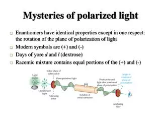
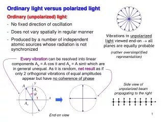
Modeling of polarized light transfer in scattering media. Monte Carlo. Introduction. The Monte Carlo method simulates the “random walk” of photons in a medium that contains absorption and scattering. . Introduction.

E N D
Modeling of polarized light transfer in scattering media Monte Carlo
Introduction The Monte Carlo method simulates the “random walk” of photons in a medium that contains absorption and scattering.
Introduction • The method is based on a set of rules that governs the movement of a photon in tissue. • The two key decisions are: • The mean free path for a scattering or absorption event. • The scattering angle.
Introduction • Monte Carlo programs estimates ensamble average quantities • The Monte Carlo method is essentially a technique for sampling a probability density function based on a computer generated random number. • Need large number of photons • Error 1/√(Number of photons)
Polarized light Monte Carlo • Main issues • Define a polarization reference plane • Propagate a Stokes vector & reference plane • Handle scattering – No Heyney Greenstain phase function • Handle scattering – Rejection method/Mie scatterers • Handle interface and exit
J.C. Ramella-Roman, S.A. Prahl , S.L. Jacques, 'Three Monte Carlo programs of polarized light transport into scattering media: part I,' Optics Express, 13, pp. 4420-4438, 2005.J.C. Ramella-Roman, S.A. Prahl, S.L. Jacques, 'Three Monte Carlo programs of polarized light transport into scattering media: part II,' Optics Express, 13, pp.10392-10405, 2005.
Three methods • Meridian Plane Monte Carlo – Today • Euler and Quaternion Monte Carlo – Tomorrow • The difference among three programs is the tracking of the reference plane
Meridian plane • Chandrasekhar was the first to envision the scattering of a photon from one location to the next in the form of meridian and scattering planes. • The photon directions, before and after scattering, are represented as points on the unit sphere and each photon direction is uniquely described by two angles q and f.
Meridian plane • q is the angle between the initial photon direction and the Z-axis. • Scattering angle • f is the angle between the meridian plane and the X-Z plane. • Azimuth angle • The photon direction is specified by a unit vector I1 • Elements of I1 are the direction cosines [ux, uy,uz]
Meridian plane • The unit vector I1and the Z-axis determine a plane COA. • This plane is the meridian plane
Launch • A photon is launched in a specific meridian/reference frame and status of polarization. • Slab geometry, perpendicular illumination, pencil beam • Direction cosines • [ux, uy, uz] = [0, 0, 1].
Launch-STEP A • Initially the meridian plane f =0, • The reference frame is initially equal to the x-z plane. • The initial Stokes vector is relative to this meridian plane.
Launch-STEP B • The status of polarization as an appropriate Stokes vector, S = [I Q U V]. • Example S=[1 1 0 0] • launched photon will be linearly polarized parallel to the x-z plane.
Move • The photon is moved as in a standard Monte Carlo program. • The photon is moved a propagation distance Ds that is calculated based on pseudo random number generated in the interval (0,1]. µt= µa +µs, µa is the absorption coefficient of the media. µs is the scattering coefficient of the media.
Move cnt. • The trajectory of the photon is specified by the unit vector I characterized by the direction cosines [ux, uy, uz]. • where xy and z are the unit vectors in the laboratory frame XYZ.
Move cnt. • The photon position is updated to a new position [x',y',z'] with the following equations:
Scatter • Three matrix multiplications are necessary to handle the scattering of a photon and track its polarization • 1. Stokes vector rotation in the scattering plane • 2. Scattering -updating the Stokes vector • 3. Return to a new meridian plane
Rotation to a new reference plane • The E field is originally defined respect to a meridian plane COA. • The field can be decomposed into its parallel and perpendicular components E|| and E. • The choice of f and q is done with the rejection method
Rotation to a new reference plane • First the Stokes vector is rotated so that its reference plane is ABO • This rotation is necessary because the scattering matrix, that defines the elastic interaction of a photon with a sphere, is specified with respect to the frame of reference of the scattering plane
1. Stokes vector rotation in the scattering plane • The Stokes vector S1 defined relative to the scattering plane (ABO) is found by multiplying by a rotational matrix R(i1) • This action corresponds to a counterclockwise rotation of an angle i1 about the direction of propagation.
Scattering • The Stokes vector is multiplied by the scattering matrix that accounts for scattering of the photon at an angle a
2. Scattering -updating the Stokes vector • The Stokes vector is multiplied by a scattering matrix, M(a). • a is the scattering angle between the direction of the photon before and after scattering.
Updating the Stokes vector • The parameters s11 , s12 , s33 , s34 are calculated with Rayleigh or Mie theory. • These terms are expressed as • S1, S2* – Mie scattering • *http://omlc.ogi.edu/calc/mie_calc.html • C. Bohren and D. R. Huffman, • Absorption and scattering of light by small • particles, (Wiley Science Paperback Series,1998).
Rejection method • The phase function P(α,β) for incident light with a Stokes vector So= [Io, Qo, Uo, Vo] is • α angle of scattering • b angle of rotation into the scattering plane
Rejection method • For unpolarized light [1 0 0 0] • The rejection method is used to generate random variables with a particular distribution.
Parallel incidence- parallel detection F B D=2.0µm D=0.01µm D=1.0µm
Parallel incidence- perpendicular detection D=2.0µm D=0.01µm D=1.0µm
Rejection method-step 1 • Generate Prand - uniform random number between 0 and 1. • arand is generated uniformly between 0 and π. • The angle arandis accepted as the new scattering angle if Prand ≤ P(arand). • If not, a new Prandand arand are generated
Rejection method-step 2 • Generate Prand - uniform random number between 0 and 1. • brand is generated uniformly between 0 and 2π. • The angle brand is accepted as the new scattering angle if Prand ≤ P(arand, brand). • If not, a new Prandand arand , brandare generated
Scattering from spherical particles Single scattering
Update of direction cosines • q and f are obtained at in the scattering step of the Monte Carlo program If |uz|≈ 1
Update of direction cosines If |uz|≠ 1
3. Return to a new meridian plane • The Stokes vector is rotated so that it is referenced to the new meridian plane COB
3. Return to a new meridian plane • The Stokes vector is multiplied by the rotational matrix R(-i2) so that it is referenced to the meridian plane COB. uare the direction cosines before scattering and û are the direction cosines after scattering.
3. Return to a new meridian plane • The Stokes vector is multiplied by the rotational matrix R(-i2) so that it is referenced to the meridian plane COB.
Summary • In summary the Stokes vector Snew after a scattering event is obtained from the Stokes vector before the scattering event S
Choice of f and a • A fundamental problem in every Monte Carlo program with polarization information is the choice of the angles a (angle of scattering) and f (angle of rotation into the scattering plane). • These angles are selected based on the phase function of the considered scatterers and a rejection method (**) • ** W. H. Press, S. A. Teukolsky, W. T. Vetterling, B. P. Flannery, Numerical Recipes in C, the art of Scientific Computing, Cambridge University Press; (1992).
Photon life • The life of a photon ends when the photon passes through a boundary or when its weight W value falls below a threshold. • Roulette is used to terminate the photon packet when W £Wth. • Gives the photon packet one chance of surviving • If the photon packet does not survive the roulette, the photon weight is reduced to zero and the photon is terminated.
Boundaries • One last rotation of the Stokes vector is necessary to put the photon polarization in the reference frame of the detector. • For simplicity we are neglecting Fresnel reflectance
Boundaries • For a photon backscattered from a slab, the last rotation to the meridian plane of the detector is of an angle y • The Stokes vector of the reflected photon is multiplied one final time by R(y). For a transmitted photon the angle y
Results • Average Stokes vector values • HI, HQ, HU, HV, VI, VQ (…) IMAGES • All you need to build an image of the Mueller matrix
Comparison with Evans’ adding-doubling* *K. F. Evans and G. L. Stephens, “A new polarized atmospheric radiative transfer model,” J. Quant. Spectrosc. Radiat Transfer. 46, 413-423, (1991).
Mueller Matrix -microspheres solutions Monte Carlo Experimental* *Cameron et al.
Mueller Matrix - microspheres solutions Monte Carlo Experimental
Results -1 Parallel experimental Parallel Monte Carlo