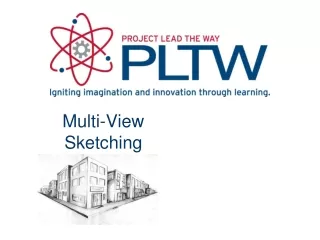
Chap 6 Multi-view Projection
Chap 6 Multi-view Projection. Instructor: M.Yaqub. Projection A view of an object is known technically as a projection. Plane of Projection Projection or view is to be drawn on a plane called Plane of Projection. Chap 6 Multi-view Projection.

Chap 6 Multi-view Projection
E N D
Presentation Transcript
Chap 6 Multi-view Projection Instructor: M.Yaqub
Projection A view of an object is known technically as a projection. Plane of Projection Projection or view is to be drawn on a plane called Plane of Projection. Chap 6 Multi-view Projection
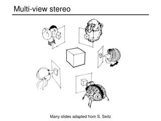
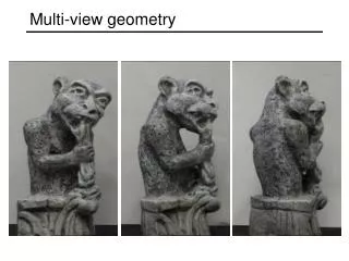
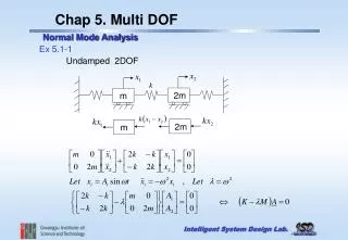
A system of views of an object formed by projectors from the object perpendicular to the plane of projection. Projectors are the line of sight and parallel for orthographic projection. Orthographic or Multi-view Projection
Frontal Plane For front view (Elevation) Horizontal Plane Top view (Plan) Profile Plane Side view (End view) Plane of Projection
H/F Folding line between the Horizontal and Front Plane. The F/P Folding line between the Front and Profile Plane. X and Y are not necessarily equal, but D1 and D2 are equal. Folding Lines
Not complete, show only what is necessary for clear description. A brake line is used to limit the partial view. For symmetry, half view (C) can be drawn on one side of the center line or broken or partial view can be drawn (d). Partial Views
Fig 6-12 is an example of two side views required and both of them are partial views.
A complete or partial view removed to another place on the sheet so that it no longer is in direct projection with any other view. Show some feature more clearly on large scale. Should be labeled as “view AA” or “view BB”. Removed View
Visualization Figure 6-16
If plane surface is perpendicular to a plane of projection, it appears as line or Edge View (EV), if parallel appears as true size (TS) surface. If at an angle, foreshortened (FS) surface. A plane surface always projects as a line or surface. Surfaces, Edges, and Corners
A straight line always projects as a straight line or as a point. A point appears as a point in every view.
A normal surface is a plane surface that is parallel to a plane of projection. It appears in true size and shape on the plane to which it is parallel, and as a vertical or a horizontal line on adjacent planes of projections. Plane A in Fig 6.24 I is a Normal Surface to the horizontal plane. Normal Surfaces
A Normal Edge is a line which is normal to the plane of projection. A point on the plane of projection to which it is perpendicular. And true line on adjacent plane. Example Edge D in Fig 6.24 I. Normal Edges
An Inclined surface is a plane surface ie perpendicular to one plane of projection but inclined to adjacent plane. It is FS to the plane to which it is incline. It is straight line to the plane to which it is perpendicular. Example, Figure 6-25 plane A. Inclined Surface
An Inclined edge is a line ie parallel to one plane of projection but inclined to adjacent plane. It is TL to the plane to which it is parallel. It is FS to the adjacent plane. Example, Figure 6-25 Edge B. Inclined Edge
An oblique surface is a plane that is incline to all planes of projection. Appear as a surface in all view. Can’t be a line. Appears as FS length. Example, Figure 6.26 II Plane C. Oblique Surfaces
An oblique edge is a line that is oblique to all planes of projection. Can not be a point in any view. Appears in all view as FS length. Example, Figure 6.26 II edge F. Oblique Edges