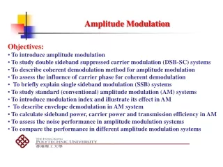
AMPLITUDE MODULATION
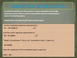
AMPLITUDE MODULATION. Amplitude modulation is the process in which amplitude of the high frequency carrier wave is varies in accordance with the instantaneous value of modulating signal. EXPRESSION FOR AMPLITUDE MODULATED WAVE. Let the modulated signal be represented as

AMPLITUDE MODULATION
E N D
Presentation Transcript
AMPLITUDE MODULATION Amplitude modulation is the process in which amplitude of the high frequency carrier wave is varies in accordance with the instantaneous value of modulating signal. EXPRESSION FOR AMPLITUDE MODULATED WAVE Let the modulated signal be represented as em = Em sinwmt …(1) And the carrier signal be represented as. ec = Ec sinwct … (2) “Depth of modulation” (m) or the “modulation index” is given by m= Em/Ec Now the amplitude of the modulated signal is given by A=Ec+ em
= Ec + Emsinwmt = Ec +mEc sinwmt = Ec [1+m sinwmt] … (3) Thus amplitude modulated signal can be represented in time domain as E = A sin0 E= Asinwct = Ec [1+msinwmt]* sinwct = Ec sinwct +mEcsinwctsinwmt = Ecsinwct +(mEc /2)*2 sinwctsinwmt = Ec sinwct +(mEc /2) [cos( wc +wm)t + cos( wc-wm)t] …(4) Thus it has been shown that the equation of an amplitude modulated wave contains three terms. The first term is identical to equation (2) and represent the the unmodulated carrier. It is thus apparent that the process of amplitude modulation has the effect of adding term to the unmodulated wave, rather than changing it.
MODULATION INDEX FOR AMPLITUDE MODULATION. • Modulation index can be practically can be calculated measured using two method. • Using an AM signal. • Using an trapezoidal display. Carrier signal Modulator Modulating signal CRO
t t (a) Modulating signal (b) Carrier signal Em Em Emax Ec Emin t (c) Amplitude modulated signal
Q.1) M = Emax-Emin Emax+Emin Sol. M=Em/Ec m = Emax - Emin/2 ….1 Ec=Emax - Em =Emax -( Emax-Emin/2 ) =Emax+Emin/2 …2 Dividing (1) by (2) M = Emax-Emin …3 Emax+Emin Equation (3) standard method of evaluating modulation index
Trapezoidal Display Method Em Ec A B t AM signal Modulated signal
In this method the Am signal is connected vertical deflection and the modulation signal is applied to the horizontal deflection plate of the oscilloscope. The display on the screen of oscilloscope is trapezoidal as shown in fig. A=2(Ec + Em) ……1 B=2( Ec-Em) ……2 Adding (1) and (2) A+B=4Ec Ec=(A + b) / 4 ……3 subtracting (1) and (2) A-B=4Em Em= (A-B) / 4 …….4 Modulation index mf = Em/ Ec = (A-b) / ( A+b )
Relative Power Distribution in AM Wave It is clear that modulated carrier wave contain more power as compared to unmodulated wave became of fact it contain two or more side band. The total power will depend upon the modulation index. Pt= Ec + ELSB + EUSB ………….(1) R R R Where all the voltage signal have r.m.s value and R represents the antenna resistance. 2 2 2 2 Pc = (Ec/ ) R =Ec /2R ……………(2) Similarly Plsb =Pusb = [ (m Ec/2) / 2 ] =m Ec / 8R ………(3) 2 2 2 2 2
Putting the value of (2) and (3) in equation (1). Then result is : The maximum power in the AM corresponding to m=1 is Pt = 1.5 Pc. This is important that relevant amplifier must be capable of handling without distortion. Current Calculation Let Icbe the unmodulated carrier current and It be the modulated current r is the resistance in which the current flow. Pt / Pc = It R/ Ic R = [ 1 + m /2 ] It / Ic = 1 + m / 2 It = Ic 1+ m / 2 Pt= Pc [ 1 + m / 2] 2 2 2 2 2 2 2
If the frequency of the carrier is made to varying in accordance with instantaneous Value of the modulating signal, the process is called FM. Expression: In FM the frequency of the carrier varies the amount by which the carrier frequency and varied from its unmodulated value is called deviation. And the deviation is perpendicular to the Instantaneous value of modulating signal. The instantaneous value of frequency of the modulated carreier is given by: f = fc + fckf Emcoswmt = fc [1 + kf Em coswmt ] ……..(1) Fc = unmodulated carrier frequency. Kf = proportionality constant Em coswmt = Instantaneous modulated voltage Frequency Modulation
Maximum Frequency deviation fmin = fc (1-kEm) fmax = fc (1+kEm)[] = fmax – fc = fc – fmin = kf Emfc ……….2 Considering again equation (1) f = fc [1 + kf Em coswmt ] w = wc [1 + kf Em coswmt ] But angular velocity W= do / dt O = wdt Put the value of w O = wc [1 + kf Em cos wmt ] dt = wct + wc kf Em sinwmt wm fmax fc fmin
O(t) = wct + sinwmt …………(3) from 2 fm The carrier wave efmt may be written as efm(t) = Ec sinO(t) Put the value of O(t) in above equation efm(t) = Ec sin (wct + sinwmt ) ………..(4) fm The modulation index of FM Mf = Max frequency deviation = ……….(5) Modulating frequency fm From equation (4) and (5) efm(t) = Ec sin (wct + Mf fm sinwmt ) ………..(4) fm efm(t) = Ec sin (wct + Mf sinwmt ) Ans.
Frequency Spectrum For FM Wav The Expression for FM is not simple. It is complex since, it is a sine of sine function. The only way to solve this equation is using Bessel’s Function. By using Bessel’s Function. The equation for FM wave can be expanded. As follows. efm = s(t)= Ec { jo (Mf) sinwct } + j1Mf { sin( wc +wm)t – sin (wc-wm)t } +j2Mf { sin(wc+2wm) t + sin (wc-2wm)t }+ j3Mf { sin( wc+3wm)t – sin (wc-3wm)t } + j4Mf { sin( wc +4wm)t – sin (wc-4wm)t } +………….(*) The FM wave constant of carrier. The first term in equation the carrier. FM consist of infinite no. of side band. All terms except first term. The amplitude of the carrier and the side band depend is depends on ‘j’ coefficient. The value of these coefficient can be term the graph.
For equation j1(Mf) denotes the value of j1 for the particular value of Mf written inside the bracket. Mf jo j1 j2 .01 ---------- ------ --------- .25 --------- -------- --------- In Mf wave, the total transmitted power always remain constant. It is not dependent upon modulation index. The region for this is that the amplitude of FM wave is constant. Pt =( a/ 2) = A Where ’A’ peak amplitude of FM wave .It is equal to Pt = A where R =1 2 2 R R 2 R
Difference Between AM and FM 1) Amplitude of AM wave will change With modulating voltage. • Transmitted power is dependent on the Modulation index. 3) Carrier power and one side band power is useful. 4) AM receiver are non immune to noise. 5) It is not possible to decrease noise further by increasing deviation Amplitude of Fm is constant. It is independent of modulation index. Transmitted power remain constant. It is interdependent on the Modulation index. All the transmitted power is useful. They are immune to noise. It is possible to decrease noise further by increasing deviation
Bandwidth = 2( + fm ) . • BW depends on . BW is much less than FM. • Ground wave and sky wave propagation is used. Therefore large area is concerned. • AM equipments for modulation are less complex. • No. of side band will be two and more constant. • Bandwidth = 2 fm • BW is large hence wide channel is required. • Space wave is used for propagation so radius of transmission is limited. • FM transmission and reception the equipment are complex. • NO. of side band having significant amplitude depends upon modulation index.
Difference Between FM and PM FM PM • S(t) = Ec sin( wct + mf sinwmt) • Frequency modulation is proportional to modulating voltage. • Mf is proportional to modulating voltage as well as the modulating frequency. • It is widely used. • It is possible to receive FM on PM receiver • Noise immunity is better than AM an PM • S(t) = Ec sin( wct + mp sinwmt) • Phase modulation is proportional to modulating voltage. • Mp is proportional only to modulating voltage. • Used in some mobile system. • It is possible to receive PM on FM receiver. • Noise immunity is better than AM but worst than PM