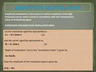
AMPLITUDE MODULATION
AMPLITUDE MODULATION. Communication Systems : Prof. Ravi Warrier. Main Topics : Double sideband modulation, demodulation Amplitude Modulation - Suppressed carrier Single sideband Vestigial Sideband Superhetrodyne AM Receiver.


AMPLITUDE MODULATION
E N D
Presentation Transcript
AMPLITUDE MODULATION Communication Systems : Prof. Ravi Warrier Main Topics :Double sideband modulation, demodulation Amplitude Modulation - Suppressed carrier Single sideband Vestigial Sideband Superhetrodyne AM Receiver AMPLITUDE MODULATION : DOUBLE SIDEBAND SUPPRESSED CARRIER(DSB-SC) m(t) = message signal , M()= its spectrum , cos(ct) =carrier signal, c =carrier frequency. (t) = m(t)cos(ct) = modulated signal, EXAMPLE : 0 0 Lower sideband (LSB) Upper sideband (USB) 0 Notice that the carrier part is missing in the spectrum of (t) (impulse functions disappeared). Therefore, this type of modulation is called AM-Double Side band Suppressed Carrier (AM-DSBSC) modulation.
Communication Systems : Prof. Ravi Warrier DEMODULATION : e(t)= (t) cos(ct) = m(t)cos2(ct) Lowpass filter e(t) to get m(t). 0 e(t) LPF Demodulation requires a local oscillator at the receiver and the frequency and phase of the local sine wave should be synchronized with the transmitter. This requires expensive hardware. Read : Tone modulation Modulators - Nonlinear modulator, switching modulators and ring modulators Frequency conversion. Important result : Multiplying two sinusoids results in two frequencies which are the sum and difference of the frequencies of the sinusoids multiplied. To change the carrier frequency c of a modulated signal to an intermediate frequency I we use an oscillator to generate a sinusoid of frequency MIX such that BPF@ I EXAMPLE : Let m(t) be as shown. m(t) (t) e1(t) SPECTRA 0 0 0
Communication Systems : Prof. Ravi Warrier EXERCISE : Let m(t)=cos(10t) and c = 200 rad/s. a) Sketch (t) = m(t)cos(ct) . b) Sketch the spectra of m(t) and (t). c) What is are upper sideband and lower sideband components of g(t) ? Express them in frequency domain and time domain. AMPLITUDE MODULATION (AM) A dc offset is added to m(t) before modulation. The last impulse functions indicate that the carrier is not suppressed in this case. For some M() shown, the modulated signal spectrum is as shown. 0 0 With this type of AM the demodulation can be performed without a local oscillator synchronized with the transmitter. EXAMPLE : m(t) has a minimum value of about -0.4. Adding a dc offset of A=1 results in A+m(t) being always positive. Therefore the positive envelope of is just A+m(t). An envelope detector can be used to retrieve this. A=1 m(t) A+m(t) 0.7 1. 0. -0.4
Communication Systems : Prof. Ravi Warrier The choice of dc offset should be such that A+m(t) should always be positive. Otherwise envelope detector cannot be used. For example, the minimum value of m(t) = -0.4 . Therefore A > |min(m(t))| for successful envelope detection. What if A< |m(t). In the previous example let A=0.3. A=0.3 A+m(t) m(t) 0.7 0 0. -0.4 Envelope detection cannot be employed in this case . The condition for envelope detection is that A+m(t) 0 for all t. Let mp be the absolute negative peak of m(t). EXAMPLE : Single-tone modulation. Let m(t)=2sin(20t) and carrier frequency be 200 rad/sec. What is the dc offset required for i) =0.5 , ii)=1. Sketch the AM signal if the dc offset used is 1. m(t)
EXERCISE : Let m(t)=2[cos(20t)+cos(40t)] and carrier frequency be 200 rad/sec. What is the dc offset required for i) =0.5 , ii)=1. [mp = 2.25 for this m(t). Why ?) Communication Systems : Prof. Ravi Warrier Sideband powers : EXERCISE : For AM wave with m(t)=2[cos(20t)+cos(40t)] calculate the efficiency if i) =0.5 , ii)=1. Generation of AM signals Read in TEXT + - m(t) AM output + - c cos(ct) DEMODULATION OF AM WAVES : 1. Rectifier detector : READ in TEXT
Communication Systems : Prof. Ravi Warrier 2.DEMODULATION USING ENVELOPE DETECTION: + vc(t) - AM signal R C EXAMPLE : Let E(t)=[A+Bcos(mt)]. Design RC for envelope detection. AM signal BANDWIDTH : AM signal bandwidth is twice the bandwidth of the modulating signal. (Why?) A 5kHz signal requires 10kHz bandwidth for AM transmission. If the carrier frequency is 1000 kHz, the AM signal spectrum is in the frequency range of 995kHz to 1005 kHz. QUADRARTURE AMPLITUDE MODULATION is a scheme that allows two signals to be transmitted over the same frequency range. READ TEXT.
Communication Systems : Prof. Ravi Warrier Single Sideband (SSB) AM Purpose : to reduce the bandwidth requirement of AM by one-half. This is achieved by transmitting only the upper sideband or the lower sidebband of the DSB AM signal. 0 0 SSB (Upper sideband) 0 Math description:
Communication Systems : Prof. Ravi Warrier Next we show that the SSB signal can be expressed in terms of m(t) and its Hilbert transform as follows. How to generate mh(t) ? M() H() Mh() Transfer function of a Hilbert transformer
Communication Systems : Prof. Ravi Warrier SSB Signal Generation : 1. Selective Filtering using filters with sharp cutoff characteristics. Sharp cutoff filters are difficult to design. The audio signal spectrum has no dc component, therefore , the spectrum of the modulated audio signal has a null around the carrier frequency.This means a less than perfect filter can do a reasonably good job of filtering the DSB to produce SSB signals. 0 2. Phase shift method using Hilbert transformer. x + m(t) ~ + Hilbert Transformer X DEMODULATION OF SSB AM SIGNAL : 1. Synchronous demodulation : SSB signal can be transmitted with carrier as well by adding a dc off set.
Communication Systems : Prof. Ravi Warrier EXAMPLE : Tone modulation : m(t)= cos(mt). What is the Hilbert transform of this m(t) ? VESTIGIAL SIDEBAND (VSB) AM : VSB is a compromise between DSB and SSB. To produce SSB signal from DSB signal ideal filters should be used to split the spectrum in the middle so that the bandwidth of bandpass signal is reduced by one half. In VSB system one sideband and a vestige of other sideband are transmitted together. The resulting signal has a bandwidth > the bandwidth of the modulating (baseband) signal but < the DSB signal bandwidth. DSB 0 SSB (Upper sideband) 0 VSB Spectrum 0 m(t) e(t) Hi() LPF Ho() Transmitter Receiver