Chapter 3. Amplitude Modulation
Chapter 3. Amplitude Modulation. Essentials of Communication Systems Engineering John G. Proakis and Masoud Salehi. Amplitude Modulation. A large number of information sources produce analog signals Analog signals can be modulated and transmitted directly, or

Chapter 3. Amplitude Modulation
E N D
Presentation Transcript
Chapter 3. Amplitude Modulation Essentials of Communication Systems Engineering John G. Proakis and Masoud Salehi
Amplitude Modulation • A large number of information sources produce analog signals • Analog signals can be modulated and transmitted directly, or • They can be converted into digital data and transmitted using digital-modulation techniques • The notion of analog-to-digital conversion : Examined in detail in Chapter 7 • Speech, music, images, and video are examples of analog signals • Each of these signals is characterized by its bandwidth, dynamic range, and the nature of the signal • Speech signals : Bandwidth of up to 4 kHz • Audio and black-and-white video • The signal has just one component, which measures air pressure or light intensity • Music signal : Bandwidth of 20 kHz • Color video • The signal has four components, namely, the red, green, and blue color components, plus a fourth component for the intensity • In addition to the four video signals, an audio signal carries the audio information in Color-TV broadcasting • Video signals have a much higher bandwidth, about 6 MHz Oh-Jin Kwon, EE dept., Sejong Univ., Seoul, Korea: http://dasan.sejong.ac.kr/~ojkwon/
3.1 INTRODUCTION TO MODULATION • The analog signal to be transmitted is denoted by m(t) • Assumed to be a lowpass signal of bandwidth W • M(f) = 0, for |f| > W • The power content of this signal is denoted by • The message signal m(t) is transmitted through the communication channel by impressing it on a carrier signal of the form • Ac: Carrier amplitude • fc : Carrier frequency • c : Carrier phase - The value of cdepends on the choice of the time origin • we assume that the time origin is chosen such that c= 0 • We say that the message signal m(t) modulates the carrier signal c(t) in either amplitude, frequency, or phase if after modulation, the amplitude, frequency, or phase of the signal become functions of the message signal • Modulation converts the message signal m(t) from lowpass to bandpass, in the neighborhood of the carrier frequency fc. Oh-Jin Kwon, EE dept., Sejong Univ., Seoul, Korea: http://dasan.sejong.ac.kr/~ojkwon/
3.2 AMPLITUDE MODULATION (AM) • In amplitude modulation, the message signal m(t) is impressed on the amplitude of the carrier signal c(t) = Accos(2fct) • This results in a sinusoidal signal whose amplitude is a function of the message signal m(t) • There are several different ways of amplitude modulating the carrier signal by m(t) • Each results in different spectral characteristics for the transmitted signal • We will describe these methods, which are called • Double sideband, suppressed-carrier AM (DSB-SC AM) • Conventional double-sideband AM • Single-sideband AM (SSB AM) • Vestigial-sideband AM (VSB AM) Oh-Jin Kwon, EE dept., Sejong Univ., Seoul, Korea: http://dasan.sejong.ac.kr/~ojkwon/
3.2.1 Double-Sideband Suppressed-Carrier AM • A double-sideband, suppressed-carrier (DSB-SC) AM signal is obtained by multiplying the message signal m(t) with the carrier signal c(t) = Accos(2fct) • Amplitude-modulated signal • An example of the message signal m(t), the carrier c(t), and the modulated signal u (t) are shown in Figure 3.1 • This figure shows that a relatively slowly varying message signal m(t) is changed into a rapidly varying modulated signal u(t), and due to its rapid changes with time, it contains higher frequency components • At the same time, the modulated signal retains the main characteristics of the message signal; therefore, it can be used to retrieve the message signal at the receiver Oh-Jin Kwon, EE dept., Sejong Univ., Seoul, Korea: http://dasan.sejong.ac.kr/~ojkwon/
Double-Sideband Suppressed-Carrier AM • Figure 3.1 An example of message, carrier, and DSB-SC modulated signals Oh-Jin Kwon, EE dept., Sejong Univ., Seoul, Korea: http://dasan.sejong.ac.kr/~ojkwon/
Spectrum of the DSB-SC AM Signal • Spectrum of the modulated signal can be obtained by taking the FT of u(t) • Figure 3.2 illustrates the magnitude and phase spectra for M(f) and U(f) • The magnitude of the spectrum of the message signal m(t) has been translated or shifted in frequency by an amount fc • The bandwidth occupancy, of the amplitude-modulated signal is 2W, whereas the bandwidth of the message signal m(t)is W • The channel bandwidth required to transmit the modulated signal u(t)is Bc= 2W Figure 3.2 Magnitude and phase spectra of the message signal m(t)and the DSB-AM modulated signal u(t) Oh-Jin Kwon, EE dept., Sejong Univ., Seoul, Korea: http://dasan.sejong.ac.kr/~ojkwon/
Spectrum of the DSB-SC AM Signal • The frequency content of the modulated signal u(t)in the frequency band | f | > fcis called the upper sideband of U(f) • The frequency content in the frequency band | f | < fcis called the lower sideband of U(f) • It is important to note that either one of the sidebands of U(f)contains all the frequencies that are in M(f) • The frequency content of U(f)for f > fccorresponds to the frequency content of M(f)for f > 0 • The frequency content of U(f)for f < - fc corresponds to the frequency content of M(f) for f < 0 • Hence, the upper sideband of U(f)contains all the frequencies in M(f) . A similar statement applies to the lower sideband of U(f) Oh-Jin Kwon, EE dept., Sejong Univ., Seoul, Korea: http://dasan.sejong.ac.kr/~ojkwon/
Spectrum of the DSB-SC AM Signal • The other characteristic of the modulated signal u(t)is that it does not contain a carrier component • As long as m(t)does not have any DC component, there is no impulse in U (f) at f = fc • That is, all the transmitted power is contained in the modulating (message) signal m(t) • For this reason, u(t)is called a suppressed-carrier signal • Therefore, u(t)is a DSB-SC AM signal. Oh-Jin Kwon, EE dept., Sejong Univ., Seoul, Korea: http://dasan.sejong.ac.kr/~ojkwon/
Power Content of DSB-SC Signals • The power content of the DSB-SC signal • Pmindicates the power in the message signal m(t) • The last step follows from the fact that m2(t) is a slowly varying signal and when multiplied by cos(4fct), which is a high frequency sinusoid, the result is a high-frequency sinusoid with a slowly varying envelope, as shown in Figure 3.5 • Since the envelope is slowly varying, the positive and the negative halves of each cycle have almost the same amplitude • Hence, when they are integrated, they cancel each other • Thus, the overall integral of m2(t)cos(4fct) is almost zero (Figure 3.6) • Since the result of the integral is divided by T, and T becomes very large, the second term in Equation (3.2.1) is zero Figure 3.5 Plot of m2(t)cos(4fct). Figure 3.6 This figure shows why the second term in Equation (3.2.1) is zero. Oh-Jin Kwon, EE dept., Sejong Univ., Seoul, Korea: http://dasan.sejong.ac.kr/~ojkwon/
Demodulation of DSB-SC AM Signals • Suppose that the DSB-SC AM signal u(t) is transmitted through an ideal channel (with no channel distortion and no noise) • Then the received signal is equal to the modulated signal, • Suppose we demodulate the received signal by • Multiplying r(t)by a locally generated sinusoid cos(2fct + ), where is the phase of the sinusoid • We pass the product signal through an ideal lowpass filter with the bandwidth W • The multiplication of r(t) with cos(2fct + ) yields Oh-Jin Kwon, EE dept., Sejong Univ., Seoul, Korea: http://dasan.sejong.ac.kr/~ojkwon/
Demodulation of DSB-SC AM Signals • The spectrum of the signal is illustrated in Figure 3.7 • Since the frequency content of the message signal m(t) is limited to W Hz, where W << fc, the lowpass filter can be designed to eliminate the signal components centered at frequency ±2 fc and to pass the signal components centered at frequency f = 0 without experiencing distortion • An ideal lowpass filter that accomplishes this objective is also illustrated in Figure 3.7 • Consequently, the output of the ideal lowpass filter (그림오류 2배 큰 모습) Figure 3.7 Frequency-domain representation of the DSB-SC AM demodulation. Oh-Jin Kwon, EE dept., Sejong Univ., Seoul, Korea: http://dasan.sejong.ac.kr/~ojkwon/
Demodulation of DSB-SC AM Signals • Note that m(t) is multiplied by cos() • Therefore, the power in the demodulated signal is decreased by a factor of cos2. • Thus, the desired signal is scaled in amplitude by a factor that depends on the phase of the locally generated sinusoid. • When 0, the amplitude of the desired signal is reduced by the factor cos(). • If = 45, the amplitude of the desired signal is reduced by 21/2 and the power is reduced by a factor of two. • If = 90, the desired signal component vanishes • The preceding discussion demonstrates the need for a phase-coherent or synchronous demodulator for recovering the message signal m(t) from the received signal • That is, the phase of the locally generated sinusoid should ideally be equal to 0 (the phase of the received-carrier signal) Oh-Jin Kwon, EE dept., Sejong Univ., Seoul, Korea: http://dasan.sejong.ac.kr/~ojkwon/
Demodulation of DSB-SC AM Signals • A sinusoid that is phase-locked to the phase of the received carrier can be generated at the receiver in one of two ways • One method is to add a carrier component into the transmitted signal, as illustrated in Figure 3.8. • We call such a carrier component "a pilot tone." • Its amplitude Ap and its power Ap2 / 2 are selected to be significantly smaller than those of the modulated signal u(t). • Thus, the transmitted signal is a double-sideband, but it is no longer a suppressed carrier signal Figure 3.8 Addition of a pilot tone to a DSB-AM signal. Oh-Jin Kwon, EE dept., Sejong Univ., Seoul, Korea: http://dasan.sejong.ac.kr/~ojkwon/
Demodulation of DSB-SC AM Signals • At the receiver, a narrowband filter tuned to frequency fc, filters out the pilot signal component • Its output is used to multiply the received signal, as shown in Figure 3.9 • We may show that the presence of the pilot signal results in a DC component in the demodulated signal • This must be subtracted out in order to recover m(t) Figure 3.9 Use of a pilot tone to demodulate a DSB-AM signal. Oh-Jin Kwon, EE dept., Sejong Univ., Seoul, Korea: http://dasan.sejong.ac.kr/~ojkwon/
Demodulation of DSB-SC AM Signals • Adding a pilot tone to the transmitted signal has a disadvantage • It requires that a certain portion of the transmitted signal power must be allocated to the transmission of the pilot • As an alternative, we may generate a phase-locked sinusoidal carrier from the received signal r(t)without the need of a pilot signal • This can be accomplished by the use of a phase-locked loop, as described in Section 6.4. Oh-Jin Kwon, EE dept., Sejong Univ., Seoul, Korea: http://dasan.sejong.ac.kr/~ojkwon/
Demodulation of DSB-SC AM Signals • Method 1: Phase comparator를 사용한 PLL 회로 • Method 2: cos(4fct ) 성분을 BPF한 후 주파수를 2:1로 분주한 신호를 사용함. Oh-Jin Kwon, EE dept., Sejong Univ., Seoul, Korea: http://dasan.sejong.ac.kr/~ojkwon/
Examples • Ex 3.2.1 • Ex 3.2.2 • Ex 3.2.3 Oh-Jin Kwon, EE dept., Sejong Univ., Seoul, Korea: http://dasan.sejong.ac.kr/~ojkwon/
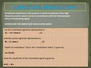
3.2.2 Conventional Amplitude Modulation • A conventional AM signal consists of a large carrier component, in addition to the double-sideband AM modulated signal • The transmitted signal is expressed mathematically as • The message waveform is constrained to satisfy the condition that |m(t)| 1 • We observe that Acm(t) cos(2fct)is a double-sideband AM signal and Accos(2fct)is the carrier component • Figure 3.10 illustrates an AM signal in the time domain • As we will see later in this chapter, the existence of this extra carrier results in a very simple structure for the demodulator • That is why commercial AM broadcasting generally employs this type of modulation Figure 3.10 A conventional AM signal in the time domain Oh-Jin Kwon, EE dept., Sejong Univ., Seoul, Korea: http://dasan.sejong.ac.kr/~ojkwon/
Conventional Amplitude Modulation • As long as |m(t)| 1, the amplitude Ac[1 + m(t)]is always positive • This is the desired condition for conventional DSB AM that makes it easy to demodulate, as we will describe • On the other hand, if m(t)< -1 for some t , the AM signal is overmodulated and its demodulation is rendered more complex • In practice, m(t)is scaled so that its magnitude is always less than unity • It is sometimes convenient to express m(t)as • where mn(t)is normalized such that its minimum value is -1 and • The scale factor a is called the modulation index, which is generally a constant less than 1 • Since |mn(t)| 1and 0 < a < 1, we have 1 + amn(t)> 0 and the modulated signal can be expressed as • which will never be overmodulated Oh-Jin Kwon, EE dept., Sejong Univ., Seoul, Korea: http://dasan.sejong.ac.kr/~ojkwon/
Spectrum of the Conventional AM Signal • If m(t) is a message signal with Fourier transform (spectrum) M(f), the spectrum of the amplitude-modulated signal u(t) is • A message signal m(t), its spectrum M(f) , the corresponding modulated signal u(t), and its spectrum U(f) are shown in Figure 3.11 • Obviously, the spectrum of a conventional AM signal occupies a bandwidth twice the bandwidth of the message signal Figure 3.11 Conventional AM in both the time and frequency domain. Oh-Jin Kwon, EE dept., Sejong Univ., Seoul, Korea: http://dasan.sejong.ac.kr/~ojkwon/
Power for the Conventional AM Signal • A conventional AM signal is similar to a DSB when m(t)is substituted with 1 + mn(t) • DSB-SC : The power in the modulated signal • where Pmdenotes the power in the message signal • Conventional AM : • where we have assumed that the average of mn(t)is zero • This is a valid assumption for many signals, including audio signals. Oh-Jin Kwon, EE dept., Sejong Univ., Seoul, Korea: http://dasan.sejong.ac.kr/~ojkwon/
Power for the Conventional AM Signal • Conventional AM, • The first component in the preceding relation applies to the existence of the carrier, and this component does not carry any information • The second component is the information-carrying component • Note that the second component is usually much smaller than the first component (a < 1, |mn(t)| < 1, and for signals with a large dynamic range, Pmn<< 1) • This shows that the conventional AM systems are far less power efficient than the DSB-SC systems • The advantage of conventional AM is that it is easily demodulated Oh-Jin Kwon, EE dept., Sejong Univ., Seoul, Korea: http://dasan.sejong.ac.kr/~ojkwon/
Power for the Conventional AM Signal • Efficiency of Conventional AM, Oh-Jin Kwon, EE dept., Sejong Univ., Seoul, Korea: http://dasan.sejong.ac.kr/~ojkwon/
Demodulation of Conventional DSB-AM Signals • The major advantage of conventional AM signal transmission is the ease in which the signal can be demodulated • There is no need for a synchronous demodulator • Since the message signal m(t) satisfies the condition |m(t)| < 1, the envelope (amplitude) 1+m(t) > 0 • If we rectify the received signal, we eliminate the negative values without affecting the message signal, as shown in Figure 3.14 • The rectified signal is equal to u(t) when u(t) > 0, and it is equal to zero when u(t) < 0 • The message signal is recovered by passing the rectified signal through a lowpass filter whose bandwidth matches that of the message signal • The combination of the rectifier and the lowpass filter is called an envelope detector Figure 3.14 Envelope detection of a conventional AM signal. Oh-Jin Kwon, EE dept., Sejong Univ., Seoul, Korea: http://dasan.sejong.ac.kr/~ojkwon/
Envelope Detector • As previously indicated, conventional DSB-AM signals are easily demodulated by an envelope detector • A circuit diagram for an envelope detector is shown in Figure 3.27 • It consists of a diode and an RC circuit, which is basically a simple lowpass filter • During the positive half-cycle of the input signal, the diode conducts and the capacitor charges up to the peak value of the input signal • When the input falls below the voltage on the capacitor, the diode becomes reverse-biased and the input disconnects from the output • During this period, the capacitor discharges slowly through the load resistor R • On the next cycle of the carrier, the diode again conducts when the input signal exceeds the voltage across the capacitor • The capacitor again charges up to the peak value of the input signal and the process is repeated Figure 3.27 An envelope detector. Oh-Jin Kwon, EE dept., Sejong Univ., Seoul, Korea: http://dasan.sejong.ac.kr/~ojkwon/
Envelope Detector • The time constant RC must be selected to follow the variations in the envelope of the carrier-modulated signal • If RC is too small, then the output of the filter falls very rapidly after each peak and will not follow the envelope of the modulated signal closely • This corresponds to the case where the bandwidth of the lowpass filter is too large • If RC is too large, then the discharge of the capacitor is too slow and again the output will not follow the envelope of the modulated signal • This corresponds to the case where the bandwidth of the lowpass filter is too small • Effect of large and small RC values Figure 3.28 • For good performance of the envelope detector, • In such a case, the capacitor discharges slowly through the resistor; thus, the output of the envelope detector, which we denote as , closely follows the message signal Figure 3.28 Effect of (a) large and (b) small RC values on the performance of the envelope detector. Oh-Jin Kwon, EE dept., Sejong Univ., Seoul, Korea: http://dasan.sejong.ac.kr/~ojkwon/
Demodulation of Conventional DSB-AM Signals • Ideally, the output of the envelope detector is of the form • where gl represents a DC component and g2is a gain factor due to the signal demodulator. • The DC component can be eliminated by passing d(t) through a transformer, whose output is g2m(t). • The simplicity of the demodulator has made conventional DSB-AM a practical choice for AM-radio broadcasting • Since there are literally billions of radio receivers, an inexpensive implementation of the demodulator is extremely important • The power inefficiency of conventional AM is justified by the fact that there are few broadcast transmitters relative to the number of receivers • Consequently, it is cost-effective to construct powerful transmitters and sacrifice power efficiency in order to simplify the signal demodulation at the receivers Oh-Jin Kwon, EE dept., Sejong Univ., Seoul, Korea: http://dasan.sejong.ac.kr/~ojkwon/
3.2.3 Single-Sideband AM • A DSB-SC AM signal required a channel bandwidth of Bc= 2W Hz for transmission, where W is the bandwidth of the message signal • However, the two sidebands are redundant • We will demonstrate that the transmission of either sideband is sufficient to reconstruct the message signal m(t)at the receiver • Thus, we reduce the bandwidth of the transmitted signal to that of the baseband message signal m(t) • In the appendix at the end of this chapter, we will demonstrate that a single-sideband (SSB) AM signal is represented mathematically as • where is the Hilbert transform of m(t)that was introduced in Section 2.6 • The plus or minus sign determines which sideband we obtain • The plus sign indicates the lower sideband • The minus sign indicates the upper sideband Oh-Jin Kwon, EE dept., Sejong Univ., Seoul, Korea: http://dasan.sejong.ac.kr/~ojkwon/
APPENDIX 3A: DERIVATION OF THE EXPRESSION FOR SSB-AM SIGNALS • Let m(t) be a signal with the Fourier transform (spectrum) M(f) • An upper single-sideband amplitude-modulated signal (USSB AM) is obtained by eliminating the lower sideband of a DSB amplitude-modulated signal • Suppose we eliminate the lower sideband of the DSB AM signal, uDSB(t)= 2Acm(t)cos2fct, by passing it through a highpass filter whose transfer function is given by • as shown in Figure 3.16. • Obviously, H(f) can be written as • where u-1(.) represents the unit-step function Oh-Jin Kwon, EE dept., Sejong Univ., Seoul, Korea: http://dasan.sejong.ac.kr/~ojkwon/
APPENDIX 3A: DERIVATION OF THE EXPRESSION FOR SSB-AM SIGNALS • Therefore, the spectrum of the USSB-AM signal is given by • Taking the inverse Fourier transform of both sides of Equation (3A.1) and using the modulation and convolution properties of the Fourier transform, as shown in Example 2.3.14 and Equation (2.3.26), we obtain • Next, we note that • which follows from Equation (2.3.12) and the duality theorem of the Fourier transform Oh-Jin Kwon, EE dept., Sejong Univ., Seoul, Korea: http://dasan.sejong.ac.kr/~ojkwon/
APPENDIX 3A: DERIVATION OF THE EXPRESSION FOR SSB-AM SIGNALS • Substituting Equation (3A.3) in Equation (3A.2), we obtain • where we have used the identities • Using Euler's relations in Equation (3A.4), we obtain • which is the time-domain representation of a USSB-AM signal. Oh-Jin Kwon, EE dept., Sejong Univ., Seoul, Korea: http://dasan.sejong.ac.kr/~ojkwon/
APPENDIX 3A: DERIVATION OF THE EXPRESSION FOR SSB-AM SIGNALS • The expression for the LSSB-AM signal can be derived by noting that • Therefore • Thus, the time-domain representation of a SSB-AM signal can generally be expressed as • where the minus sign corresponds to the USSB-AM signal, and the plus sign corresponds to the LSSB-AM signal Oh-Jin Kwon, EE dept., Sejong Univ., Seoul, Korea: http://dasan.sejong.ac.kr/~ojkwon/
Single-Sideband AM • The SSB-AM signal u(t)may be generated by using the system configuration shown in Figure 3.15 • The method shown in Figure 3.15 employs a Hilbert-transform filter • Another method, illustrated in Figure 3.16, generates a DSB-SC AM signal and then employs a filter that selects either the upper sideband or the lower sideband of the double-sideband AM signal Figure 3.15 Generation of a lower single-sideband AM signal. Figure 3.16 Generation of a single-sideband AM signal by filtering one of the sidebands of a DSB-SC AM signal. Oh-Jin Kwon, EE dept., Sejong Univ., Seoul, Korea: http://dasan.sejong.ac.kr/~ojkwon/
Demodulation of SSB-AM Signals • To recover the message signal m(t) in the received SSB-AM signal, we require a phase-coherent or synchronous demodulator, as was the case for DSB-SC AM signals • For the USSB signal • By passing the product signal in Equation (3.2.12) through an ideal lowpass filter, the double-frequency components are eliminated, leaving us with • Note that the phase offset not only reduces the amplitude of the desired signal m(t) by cos, but it also results in an undesirable sideband signal due to the presence of in yl(t) • The latter component was not present in the demodulation of a DSBSC signal • However, it is a factor that contributes to the distortion of the demodulated SSB signal Oh-Jin Kwon, EE dept., Sejong Univ., Seoul, Korea: http://dasan.sejong.ac.kr/~ojkwon/
Demodulation of SSB-AM Signals • The transmission of a pilot tone at the carrier frequency is a very effective method for providing a phase-coherent reference signal for performing synchronous demodulation at the receiver • Thus, the undesirable sideband-signal component is eliminated • However, this means that a portion of the transmitted power must be allocated to the transmission of the carrier • The spectral efficiency of SSB AM makes this modulation method very attractive for use in voice communications over telephone channels (wirelines and cables) • In this application, a pilot tone is transmitted for synchronous demodulation and shared among several channels • The filter method shown in Figure 3.16, which selects one of the two signal sidebands for transmission, is particularly difficult to implement when the message signal m(t) has a large power concentrated in the vicinity of f = 0 • In such a case, the sideband filter must have an extremely sharp cutoff in the vicinity of the carrier in order to reject the second sideband • Such filter characteristics are very difficult to implement in practice Oh-Jin Kwon, EE dept., Sejong Univ., Seoul, Korea: http://dasan.sejong.ac.kr/~ojkwon/
Demodulation of SSB-AM Signals • Another method Envelope Detector Oh-Jin Kwon, EE dept., Sejong Univ., Seoul, Korea: http://dasan.sejong.ac.kr/~ojkwon/
기출문제 • 2004년 1, 2번문제 • 2008년 1번 문제 • 2006년 6번 문제 Oh-Jin Kwon, EE dept., Sejong Univ., Seoul, Korea: http://dasan.sejong.ac.kr/~ojkwon/
3.2.4 Vestigial-Sideband AM • The stringent-frequency response requirements on the sideband filter in an SSB-AM system can be relaxed by allowing vestige, which is a portion of the unwanted sideband, to appear at the output of the modulator • Thus, we simplify the design of the sideband filter at the cost of a modest increase in the channel bandwidth required to transmit the signal • The resulting signal is called vestigial-sideband (VSB) AM • This type of modulation is appropriate for signals that have a strong low-frequency component, such as video signals • That is why this type of modulation is used in standard TV broadcasting Oh-Jin Kwon, EE dept., Sejong Univ., Seoul, Korea: http://dasan.sejong.ac.kr/~ojkwon/
Vestigial-Sideband AM • To generate a VSB-AM signal, we begin by generating a DSB-SC AM signal and passing it through a sideband filter with the frequency response H(f ), as shown in Figure 3.17 In the time domain, the VSB signal may be expressed as • where h(t)is the impulse response of the VSB filter • In the frequency domain, the corresponding expression is Figure 3.17 Generation of vestigial-sideband AM signal. Oh-Jin Kwon, EE dept., Sejong Univ., Seoul, Korea: http://dasan.sejong.ac.kr/~ojkwon/
Vestigial-Sideband AM • To determine the frequency-response characteristics of the filter, we will consider the demodulation of the VSB signal u(t) • We multiply u(t) by the carrier component cos2fctand pass the result through an ideal lowpass filter, as shown in Figure 3.18 • Thus, the product signal is • or equivalently, Figure 3.18 Demodulation of VSB signal. Oh-Jin Kwon, EE dept., Sejong Univ., Seoul, Korea: http://dasan.sejong.ac.kr/~ojkwon/
Vestigial-Sideband AM • If we substitute U( f ) from Equation (3.2.15)into Equation (3.2.16), we obtain • The lowpass filter rejects the double-frequency terms and passes only the components in the frequency range | f|W • Hence, the signal spectrum at the output of the ideal lowpass filter is • The message signal at the output of the lowpass filter must be undistorted • Hence, the VSB-filter characteristic must satisfy the condition Figure 3.19 VSB-filter characteristics. Oh-Jin Kwon, EE dept., Sejong Univ., Seoul, Korea: http://dasan.sejong.ac.kr/~ojkwon/
Vestigial-Sideband AM • We note that H(f)selects the upper sideband and a vestige of the lower sideband • It has odd symmetry about the carrier frequency fcin the frequency range fc- fa< f < fc+ fa, where faisa conveniently selected frequency that is some small fraction of W, i.e., fa<< W • Thus, we obtain an undistorted version of the transmitted signal • Figure 3.20 illustrates the frequency response of a VSB filter that selects the lower sideband and a vestige of the upper sideband • In practice, the VSB filter is designed to have some specified phase characteristic • To avoid distortion of the message signal, the VSB filter should have a linear phase over its passband fc- fa | f | fc + W Figure 3.20 Frequency response of the VSB filter for selecting the lower sideband of the message signals. Oh-Jin Kwon, EE dept., Sejong Univ., Seoul, Korea: http://dasan.sejong.ac.kr/~ojkwon/
Power-Law Modulation 3.3 IMPLEMENTATION OF AM MODULATORS AND DEMODULATORS • where vi(t) is the input signal, vo(t) is the output signal, and the parameters (al, a2) are constants • Then, if the input to the nonlinear device is • Its output • The output of the bandpass filter with a bandwidth 2W centered at f = fcyields • where 2a2|m(t)|/al < 1 by design • Thus, the signal generated by this method is a conventional AM signal Oh-Jin Kwon, EE dept., Sejong Univ., Seoul, Korea: http://dasan.sejong.ac.kr/~ojkwon/
Switching Modulator • Another method for generating an AM-modulated signal is by means of a switching modulator • Such a modulator can be implemented by the system illustrated in Figure 3.24(a) • The sum of the message signal and the carrier vi (t), which is given by Equation (3.3.2), are applied to a diode that has the input-output voltage characteristic shown in Figure 3.24(b), where Ac>> m(t) • The output across the load resistor is simply Figure 3.24 Switching modulator and periodic switching signal. Oh-Jin Kwon, EE dept., Sejong Univ., Seoul, Korea: http://dasan.sejong.ac.kr/~ojkwon/
Switching Modulator • This switching operation may be viewed mathematically as a multiplication of the input vi(t) with the switching function s(t), i.e., • where s(t) is shown in Figure 3.24(c) • Since s(t) is a periodic function, it is represented in the Fourier series as • The desired AM-modulated signal is obtained by passing vo(t) through a bandpass filter with the center frequency f = fcand the bandwidth 2W • At its output, we have the desired conventional AM signal Oh-Jin Kwon, EE dept., Sejong Univ., Seoul, Korea: http://dasan.sejong.ac.kr/~ojkwon/
Balanced Modulator • A relatively simple method for generating a DSB-SC AM signal is to use two conventional-AM modulators arranged in the configuration illustrated in Figure 3.25 • For example, we may use two square-law AM modulators as previously described • Care must be taken to select modulators with approximately identical characteristics so that the carrier component cancels out at the summing junction Figure 3.25 Block diagram of a balanced modulator. Oh-Jin Kwon, EE dept., Sejong Univ., Seoul, Korea: http://dasan.sejong.ac.kr/~ojkwon/
Ring Modulator • Another type of modulator for generating a DSB-SC AM signal is the ring modulator illustrated in Figure 3.26 • The switching of the diodes is controlled by a square wave of frequency fc, denoted as c(t), which is applied to the center taps of the two transformers • When c(t)> 0, the top and bottom diodes conduct, while the two diodes in the cross-arms are off • In this case, the message signal m(t)is multiplied by +1 • When c(t)< 0, the diodes in the cross-arms of the ring conduct, while the other two diodes are switched off • In this case, the message signal m(t)is multiplied by -1. • Consequently, the operation of the ring modulator may be described mathematically as a multiplier of m(t)by the square-wave carrier c(t), i.e., Figure 3.26 Ring modulator for generating a DSB-SC AM signal. Oh-Jin Kwon, EE dept., Sejong Univ., Seoul, Korea: http://dasan.sejong.ac.kr/~ojkwon/
Ring Modulator • Since c(t) is a periodic function, it is represented by the Fourier series: p49 ex2.2.2 및 switching modulation 부문 참조 • The desired DSB-SC AM signal u(t)is obtained by passing vo(t)through a bandpass filter with the center frequency f, and the bandwidth 2W • The balanced modulator and the ring modulator systems, in effect, multiply the message signal m(t)with the carrier to produce a DSB-SC AM signal • The multiplication of m(t) with Accos(wct)is called a mixing operation • Hence, a mixer is basically a balanced modulator • The method shown in Figure 3.15 for generating an SSB signal requires two mixers • Two balanced modulators, in addition to the Hilbert transformer • On the other hand, the filter method illustrated in Figure 3.16 for generating an SSB signal requires a single balanced modulator and a sideband filter Oh-Jin Kwon, EE dept., Sejong Univ., Seoul, Korea: http://dasan.sejong.ac.kr/~ojkwon/
3.4 SIGNAL MULTIPLEXING • When we use a message signal m(t) to modulate the amplitude of a sinusoidal carrier, we translate the message signal by an amount equal to the carrier frequency fc • If we have two or more message signals to transmit simultaneously over the communication channel, we can have each message signal modulate a carrier of a different frequency, where the minimum separation between two adjacent carriers is either 2W (for DSB AM) or W (for SSB AM), where W is the bandwidth of each of the message signals • Thus, the various message signals occupy separate frequency bands of the channel and do not interfere with one another during transmission • Combining separate message signals into a composite signal for transmission over a common channel is called multiplexing • There are two commonly used methods for signal multiplexing: • Time-division multiplexing • Time-division multiplexing is usually used to transmit digital information; this will be described in a subsequent chapter. • Frequency-division multiplexing • Frequency-division multiplexing (FDM) may be used with either analog or digital signal transmission Oh-Jin Kwon, EE dept., Sejong Univ., Seoul, Korea: http://dasan.sejong.ac.kr/~ojkwon/