Chapter 3: Amplitude Modulation (Reception)
Chapter 3: Amplitude Modulation (Reception). Chapter 3: Amplitude Modulation Reception. Receiver Characteristics AM Detection Superheterodyne Receivers Superheterodyne Tuning. 3.1 Receiver Characteristics. Receiver Characteristics. 3.1 Receiver Characteristics.

Chapter 3: Amplitude Modulation (Reception)
E N D
Presentation Transcript
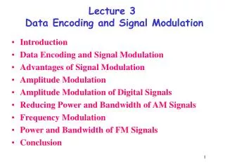
Chapter 3: Amplitude Modulation Reception • Receiver Characteristics • AM Detection • Superheterodyne Receivers • Superheterodyne Tuning
3.1 Receiver Characteristics Receiver Characteristics
3.1 Receiver Characteristics Given what we’ve covered so far about AM transmitters, if you were to envision an AM receiver, what would the block diagram look like?
3.1 Receiver Characteristics Tuned Radio Frequency (TRF) Receiver • This design is called a Tuned Radio Frequency (TRF) receiver and is exactly how the first radios were built (AM broadcast). • The problem with this design, as we will see, is that each of the three stages were preceded by a separate variable-tuned circuit. This meant that if you wanted to change the radio station, you had to: • Adjust all three knobs just right • Have a good deal of time and patience • Likely have a degree in engineering…. Let’s see why!
3.1 Receiver Characteristics Sensitivity – the minimum input signal (usually expressed as a voltage) required to produce a specified output signal or sometimes just to provide a discernible output “How strong a radio signal do I need to listen to my tunes?!”
3.1 Receiver Characteristics Receiver Sensitivity is largely governed by two characteristics: The amount of gain provided • The more we amplify a signal, the smaller that signal can be to produce an acceptable output level • Since we can easily add more amplification stages, this is the easier characteristic to increase The receiver’s noise characteristics • The input signal must be greater than the noise at the receiver input • This baseline noise level at the receiver’s input is also known as the Noise Floor • Getting noise figures below a given level is by far the greater challenge
3.1 Receiver Characteristics Selectivity – the extent to which a receiver can differentiate between the desired signal and other frequencies (which may include unwanted radio signals and noise)
3.1 Receiver Characteristics Receiver Selectivity is a double edged sword: If the receiver is overly selective • We can lose fidelity in the intelligence signal • This can result in loss of quality If the receiver is under selective ( excessively selective) • We can get bleed over from other stations • Also, remember external noise is directly proportional to the bandwidth, thus if we increase the bandwidth we are listening to, we also increase the noise
3.1 Receiver Characteristics Let’s take an example: What is the approximate bandwidth of audible signals 15 kHz If the intelligence is 15 kHz, how far will the sidebands extend above and below the target frequency? 15 kHz • Therefore, what would be the optimum receiver selectivity for AM? 30 kHz Therefore, if we used a 5kHz bandwidth, the upper/lower sidebands would only extend 2.5 kHz beyond the carrier and our intelligence would include a maximum of 2.5kHz, resulting in very poor fidelity!
3.1 Receiver Characteristics “OK, so why not simply set the bandwidth of all AM radio stations to 30 kHz, then the user can tune to the station they want, get full-fidelity, and hear no garbage?”
3.1 Receiver Characteristics Unfortunately, it’s not that simple. This is where the problem with TRF receivers come in. Let’s again take another example: The AM broadcast band spans from 550 to 1550 kHz. Let’s look more closely at a hypothetical EE Talk Radio:
3.1 Receiver Characteristics EE Talk Radio transmits AM on 1000 kHz. If we want the full-fidelity 30 kHz bandwidth, what Q value must our receiver circuit have? Hint: Remember from chapter 1
3.1 Receiver Characteristics The receiver should have a Q value of ~33.3 What happens when the listener, wants to tune to a different radio station?
3.1 Receiver Characteristics Let’s assume the listener subsequently wants to listen to 610. The Q of a tuned circuit remains fairly constant even as the capacitance is changed. What happens? We’ve lost almost half our bandwidth! (this probably won’t make much of a difference for WIOD, but on a station worth listening to, we might lose something!)
3.1 Receiver Characteristics Similarly, what happens if the user listens to 1200 AM? In this case, we’re able to get full-fidelity, but also lots of noise and distortion!
A TRF is to be designed with a single tuned circuit using a 10-µH inductor: Calculate the capacitance range required of the variable capacitor to tune from 550 to 1550 kHz An ideal 10-kHz BW is to occur at 1100 kHz. Determine the required Q. Calculate the BW at 550 kHz and at 1550 kHz. (a) (c) (b) @ 550 kHz, BW = 5 kHz @ 1550 kHz, BW = 14.1 kHz 110 @ 550 kHz, C = 8.37nF @ 1550 kHz, C = 1.06 nF
3.1 Receiver Characteristics “This was the primary issue with TRF receivers, and why a listener couldn’t simply change to a different frequency but had to re-tune multiple stages of the receiver. This led to the development of superheterodyne receivers which will soon be discussed.”
3.2 AM Detection AM Detection
REVIEW A DC Level Components at each of the two frequencies Components at the sum and difference frequencies Harmonics of the original two frequencies What frequency components are generated when two different frequencies are passed through a nonlinear device?
REVIEW The carrier and sidebands are separated in frequency by an amount equal to the intelligence frequency. At transmission, ideally we filter out everything but the carrier and the side-bands. How far are the carrier and sidebands separated in frequency?
3.2 AM Detection AM Transmission Process Input Signal AM Output
3.2 AM Detection AM Reception Process AM Signal AM Output
3.2 AM Detection The original intelligence!
3.2 AM Detection AM Reception Process AM Signal Output
3.2 AM Detection Diode Detector Circuit • One of the simplest and most effective AM detectors • Provides a nearly ideal nonlinear resistance curve • Can handle high power signals, no practical limit to the amplitude of the input signal • Highly efficient, when properly designed > 90% efficiency • Develops a DC voltage for automatic gain control • Distortion levels are acceptable for most AM applications
3.2 AM Detection Diode Detector 1. First we have the modulated carrier as it is introduced to the tuned circuit made up of LC1 Diode IV Curve
3.2 AM Detection Diode Detector 2. Since the diode conducts only on the positive half cycles, this circuit removes all of the negative half-cycles Diode IV Curve
3.2 AM Detection Diode Detector 3. Without yet considering C2, the average output of the waveform is shown below. Notice that although the average voltage of the input signal is 0, since the diode only conducts on positive, the average output voltage across R is > 0 Diode IV Curve
3.2 AM Detection Diode Detector 4. C2 and R make up a low-pass filter which effectively removes the now unnecessary carrier frequency. C2 charges quickly through the small resistance of the diode, but discharges slowly through the resistance R Diode IV Curve
3.2 AM Detection Diode Detector 5. Finally, the DC component of the waveform is blocked by the final capacitor C3. (Although in practice we usually use this DC component for providing automatic volume gain control). Diode IV Curve
3.2 AM Detection It’s important to carefully select the components used in the Diode detector. For example, the value of RC2 is particularly important. Circuit Desired Output Input to Detector from a Pulse
3.2 AM Detection It’s important to carefully select the components used in the Diode detector. For example, the value of RC2 is particularly important. Circuit RC2 Time constant too long Input to Detector from a Pulse
3.2 AM Detection It’s important to carefully select the components used in the Diode detector. For example, the value of RC2 is particularly important. Circuit RC2 Time constant too short Input to Detector from a Pulse
3.2 AM Detection It’s important to carefully select the components used in the Diode detector. For example, the value of RC2 is particularly important. Thus, component selection is a trade-off: The load resistor R must be large because it is essentially a voltage divider with the internal diode resistance, and we want as much of the voltage at the output as possible. However, it must not become so large that C2 becomes small enough compared to the internal junction capacitance C1 that it tries to discharge through C1 Circuit Input to Detector from a Pulse
3.3 Superheterodyne Receivers Superheterodyne Receivers
REVIEW The selectivity of a circuit changed based upon the frequency of the carrier signal, which results in multiple stages needing to be tuned independently each time the carrier frequency is changed. What was the basic problem/flaw with early TRF systems?
3.3 Superheterodyne Receivers Ensure the carrier frequency passed to the circuit is always the same! How can we avoid having to independently change the tuning of the various stages?
3.3 Superheterodyne Receivers The variable-selectivity problem of TRF systems led to the development of Superheterodyne receivers in the early 1930s. This basic circuit continues to be used now. “All that Superheterodyne receiver’s do is move the frequency of the incoming signal to a set frequency that the rest of our circuit is always tuned to!”
3.3 Superheterodyne Receivers Block Diagram of a Superheterodyne Receiver
3.3 Superheterodyne Receivers 1. The first stage the standard RF amplifier that we have seen before. It may or may not be required based on factors we will discuss later.
3.3 Superheterodyne Receivers • 2. The second stage is the mixer and is where the superheterodyne magic occurs. The mixer accepts 2 inputs: • The amplified RF signal • A steady-sine wave from the Local oscillator (LO) • This produces a new set of sum and difference frequencies. It’s output is an AM signal with a constant carrier frequency regardless of the transmitter’s frequency.
3.3 Superheterodyne Receivers 3. The third stage is the intermediate-frequency (IF) amplifier which provides the bulk of the amplification. Note that unlike in TRF, however, the IF amplifier can be tuned to a fixed frequency allowing for a constant BW over the entire band of the receiver. This is the entire purpose of the superheterodyne receiver.
3.3 Superheterodyne Receivers 4. Finally, the rest of the circuit is identical to what we have already discussed. The amplified signal is passed to the detector circuit which is then amplified and sent to our speakers
3.3 Superheterodyne Receivers Finally, note that the detector feeds back some of the DC from the signal to the IF/Mixer/RF stages. This is for Automatic Gain Control (AGC) which will be discussed.
3.3 Superheterodyne Receivers As discussed, the magic occurs because of the Mixer stage. The purpose of the mixer is to convert any incoming frequency to a set fixed frequency that the subsequent stages are tuned for. The Mixer is simply another non-linear device which will produce the same components we have seen previously. Let’s take an example: Assume a 1000 kHz carrier a 1 kHz intelligence a 1455 kHz local oscillator
3.3 Superheterodyne Receivers What will be the Mixer output components?
3.3 Superheterodyne Receivers Notice that the input to the IF stage is the frequency it has been tuned for, the signal passing through the IF stage is a replica of the original AM signal.
The key is that the frequency of the local-oscillator (LO) must be tied to the frequency we want to receive. For example, if we want to tune up from 1000 kHz to 1600 kHz, that’s a rise of the 600 kHz. We simply need to increase the frequency of the LO by 600 kHz! This is great! But, what if I want to change the frequency? Let’s say that we want to listen to 1600 kHz. The difference between 1600 kHz and 1455 kHz isn’t equal to 455 kHz. What can we do?