Chapter 5 Modulation Techniques for Mobile Radio
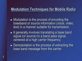
Chapter 5 Modulation Techniques for Mobile Radio. Modulation Techniques for Mobile Radio. Amplitude Modulation Angle Modulation Digital Modulation-an Overview Pulse Shaping Techniques Linear Modulation Techniques Constant Envelope Modulation

Chapter 5 Modulation Techniques for Mobile Radio
E N D
Presentation Transcript
Modulation Techniques for Mobile Radio Amplitude Modulation Angle Modulation Digital Modulation-an Overview Pulse Shaping Techniques Linear Modulation Techniques Constant Envelope Modulation Combined Linear/Constant Envelope Modulation Techniques Spread Spectrum Modulation Techniques
Frequency Modulation vs. Amplitude Modulation FM signals have all their information in phase or frequency of the carrier AM signals have all their information in the amplitude of the carrier Frequency modulation has better noise immunity when compared to amplitude modulation AM signals are able to occupy less bandwidth as compared to FM signals Frequency modulation exhibits a so-called capture effect characteristic
Amplitude Modulation AM signal can be represented as (see Fig. 1) For a sinusoidal modulating signal the modulation index is given by The spectrum of an AM signal can be show to be (see Fig. 2)
Angle Modulation The two most important classes of angle modulation being frequency modulation and phase modulation Frequency modulation (FM) can be represented as Ac : amplitude of the carrier fc : carrier frequency kf: frequency deviation constant Phase modulation (PM) can be represented as k : phase deviation constant
FM modulation Methods Direct method (see Fig. 3) The carrier frequency is directly varied in accordance with the input modulating signal Indirect method (see Fig. 4) A narrowband FM signal is generated using a balanced modulator and frequency multiplication is used to increase both the frequency deviation and the carrier frequency to the required lever, can be expressed as
FM Detection Technique Slope Detector (see Fig. 5) Zero-crossing Detector (see Fig.6) PLL for FM Detection (see Fig. 7) Quadrature Detection (see Fig. 8)
FM Detection Technique Slop Detector 5
FM Detection Technique Zero-crossing Detector 6
FM Detection Technique PLL for FM Detection 7
FM Detection Technique Quadrature detection 8
Digital Modulation-an Overview Factors that influence the choice of digital modulation power efficiency bandwidth efficiency
Digital Modulation-an Overview Bandwidth and power spectral density of digital signals the power spectral density of a random signal w(t) is define as [1] the PSD of the bandpass signal is given by Where Pg(f) is the PSD of g(t), and g(t) is the complexbaseband envelop
Pulse Shaping Techniques Nyquist criterion for ISI cancellation Raised cosine rolloff filter (see Fig. 9-10)
Linear Modulation Techniques • Digital modulation techniques are classified as linear and nonlinear. • The amplitude of transmitted signal, s(t), varies linearly with the modulating digital signal, m(t).
Binary Phase Shift Keying (BPSK) • The information of the transmitted signal is modulated into the phase of the carrier signal. 11
Coherent BPSK Receiver with carrier recovery circuits • The received BPSK signal • The bit error rate in an AWGN channel 12
Differential Phase Shift Keying (DPSK) • A noncoherent form of PSK • The input binary sequence is differentially encoded firstly. • An example • The bit error rate in an AWGN channel {mk} 1 0 0 1 0 1 1 0 {dk-1} 1 1 0 1 1 0 0 0 {dk} 1 1 0 1 1 0 0 0 1 13 14
Quadrature Phase Shift Keying (QPSK) • 2 bits are transmitted an a signal modulation symbol. • Therefore, QPSK has twice the bandwidth efficiency of BPSK. 15
Spectrum and Bandwidth of QPSK Signals • The null-to-null RF bandwidth is equal to the bit rate Rb. • The BW is half of a BPSK signal. • The bit error rate in an AWGN channel 16
QPSK Signal Transmission Technique • The bit stream m(t) is split into two bit streams mI(t) and mQ(t) (in-phase and quadrature stream). • The two binary streams are separately modulated by two carriers, which are in quadrature. 17
Coherent QPSK Signal Detection Technique • The frontend bandpass filter remove the out-of-band noise and adjacent channel interference. • The filtered output is split into two parts, and each part is coherently demodulated using in-phase and quadrature carriers. 18
Offset QPSK • OQPSK signaling is similar to QPSK, expect for the time alignment of the even and odd bit streams. • Thus, OQPSK can eliminate 180° phase transition, and prevent the signal envelope to go to zero. 19
/4 QPSK • /4 QPSK is a quadrature phase shift keying technique. • It offers a compromises between OQPSK and QPSK. • The maximum phase change of /4 QPSK is limited to 135° • An extremely attractive feature of /4 QPSK is that it can be noncoherently detected. • Further, it has been found that in the presence of multipath spread and fading, /4 QPSK performs better than OQPSK [2].
Constellation diagram of /4 QPSK signal and Carrier Phase Shifts corresponding to input bit pairs Information bits Phase shift k 1 1 /4 0 1 3/4 0 0 - 3/4 1 0 -/4 20
/4 QPSK Detection Techniques • Baseband differential detector (see Fig. 22) • IF differential detection (see Fig. 23) • FM discriminator (see Fig. 24)
Constant Envelope Modulation • The constant envelope family of modulations has following advantage [4] : • Power efficient Class C amplifiers can be used without introducing degradation in the spectrum occupancy of the transmitted signal. • Low out-of-band radiation of the order of -60 dB to -70 dB can be achieved. • Limiter-discriminator detection can be used, which simplified receiver design and provides high immunity against random FM noise and signal fluctuations due to Rayleigh fading
Binary Frequency Shift Keying (BFSK) • The information of the transmitted signal is modulated into the frequency of the carrier signal. • In general, an FSK signal may be represented as
Detection of Binary FSK Coherent 25 Noncoherent 26
Minimum Shift Keying (MSK) • Minimum shift keying (MSK) is a special type of continuous phase-frequency shift keying (CPFSK). • MSK is sometimes referred to as fast FSK, as the frequency spacing used is only half as much as that used in conventional noncoherent FSK [5]. • An MSK signal also can be thought of as a special form of OQPSK where the baseband rectangular pulses are replaced with half-sinusoidal pulses [6].
MSK Power Spectrum • From this figure, the MSK spectrum has lower sidelobes than QPSK and OQPSK. 27
Gaussian Minimum Shift Keying (GMSK) • GMSK is a simple binary modulation scheme which may be viewed as a derivative of MSK. • In GMSK, the sidelobe levels of the spectrum are further reduced by passing the modulating NRZ data waveform through a premodulation Gaussian pulse-shaping filter [7]. • In practice, GMSK is most attractive for its excellent power efficiency (due to the constant envelope).
GMSK transmitter using direct FM generation • The impulse response of the GMSK premodulation filter 30
Combined Linear/Constant Envelope Modulation Techniques • Digital baseband data may be sent by varying both the envelope and phase (frequency) of an RF carrier. • This can offer two degrees of freedom, thus such modulation techniques are called M-ary modulation. • In M-ary signaling scheme, two or more bits are grouped together to form symbols. • Depending on whether the amplitude, phase, or frequency of the carrier is varied, the modulation scheme is called M-ary ASK, M-ary PSK, or M-ary FSK. • M-ary modulation schemes achieve better bandwidth efficiency at the expense of power efficiency.