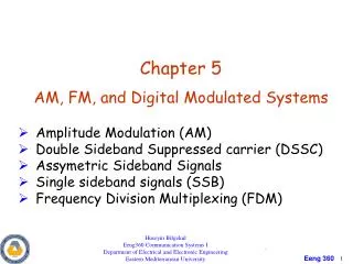
Chapter 5 Digital Modulation Systems
Chapter 5 Digital Modulation Systems. Binary Bandpass Signalling Techniques OOK BPSK FSK. Huseyin Bilgekul EEE 461 Communication Systems II Department of Electrical and Electronic Engineering Eastern Mediterranean University. Digital Modulation. Keying Schemes.

Chapter 5 Digital Modulation Systems
E N D
Presentation Transcript
Chapter 5Digital Modulation Systems • Binary Bandpass Signalling Techniques • OOK • BPSK • FSK Huseyin Bilgekul EEE 461 Communication Systems II Department of Electrical and Electronic Engineering Eastern Mediterranean University
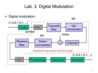
Digital Modulation Keying Schemes Pulse Modulation Schemes Either the frequency or phase of a carrier signal is keyed in response to patterns of 1s and 0s. The basic idea is to use a pulse train as the carrier signal Passband PAM Modulation PWM modulation
Digital Modulation Carrier signal: Ac cos (2pfct +θ) Modulation: m(t) Modulated signal: Ac (t) cos (2pfc(t) t +θ(t)) m(t); discrete Vary Vary amplitude frequency & phase • Multilevel • QPSK • MPSK • QAM • Binary • OOK • BPSK • DPSK • FSK Variations are discrete!!!!!
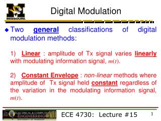
5-9 Binary Modulated Bandpass signaling: • The most common binary bandpass signaling techniques are: • On –Off keying (OOK), • OOK is also called amplitude shift keying (ASK), which consists of keying (switching) a carrier sinusoid on and off with a uni-polar binary signal. Morse code radio transmission is an example of this technique. OOK was one of the first modulation techniques to be used and precedes analog communication systems. • Binary Phase-Shift Keying (BPSK), • BPSK consists of shifting the phase of a sinusoidal carrier 0 or 180 with a unipolar binary signal. BPSK is equivalent to PM signaling with a digital waveform. • Frequency-Shift Keying (FSK), • FSK consists of shifting the frequency of a sinusoidal carrier from a mark frequency to a space frequency, according to the baseband digital signal. FSK is identical to modulating an FM carrier with a binary digital signal.
Binary bandpass signaling techniques 1 0 1 0 1 0 Change in Phase Change in Freq Note: • Digitally modulated bandpass signals are generated by using the complex envelopes for AM,PM,FM or QM • Modulating signal m(t) is a digital signal given by binary or multilevel signals
Carrier Cos(2fct) OOK output Acm(t)Cos(2fct) Message m(t) On-Off Keying (OOK) / Amplitude Shift Keying (ASK) Key/ Switch • The complex envelope is • The OOK signal is represented by • The PSD of this complex envelope is given by where m(t) has a peak value of So that s(t) has an average normalized power of
On-Off Keying (OOK) 1 0 1 0 1 0 1 Message m(t) Unipolar Modulation m(t) Bipolar Modulation s (t) OOK signal Tb – Bit period ; R – Bit rate
Spectrum of On-Off Keying (OOK) • PSD of the bandpass waveform is given by • For OOK • Null-to-Null bandwidth is and absolute bandwidth is • The Transmission bandwidth is Where B is the baseband bandwidth • Using Raised cosine pulse shape the bandwidth is:
Binary output Envelope Detector OOK in Detection of OOK • Non-Coherent Detection • Coherent Detection with Low-pass filter Binary output LPF OOK in
Optimum Detection of OOK • For optimum detection (Lowest Bit Error Rate BER) of OOK product detection with MATCHED Filter processing is required.
Binary Phase Shift Keying (BPSK) • The BPSK signal is represented by To make this problemsimplelet, Data term Pilot carrier term • The level of the pilot carrier term is set by the value of the Peak DeviationΔθ = Dp • The digital modulation index ‘h’ is defined as 2∆θ – maximum peak-to-peak deviation during time Ts • If Dp is small, then there is little power in data term & more in pilot term • To maximize performance (minimum probability of error) Optimum case : Optimum BPSK signal :
Message: m(t) Carrier:Cos(2fct) BPSK output AcCos(2fct+Dpm(t)) -90 Phase shift Binary Phase Shift Keying (BPSK) Generation: 1 0 1 0 1 0 1 Message m(t) Unipolar Modulation m(t) Bipolar Modulation s(t) BPSK output
Spectrum of Binary Phase Shift Keying (BPSK) • The complex envelope Optimum BPSK is given by • The PSD for this complex envelope is given by • PSD of the bandpass waveform is given by Average normalized power of s(t) : 2R = 2/Tb Null-to-Null BW PSD of optimum BPSK
If Dp /2 Pilot exists fc 2R = 2/Tb Binary Phase Shift Keying (BPSK) Power Spectral Density (PSD) of BPSK: ( Non Optimum BPSK)
Message: m(t) Cos(2f1t) FSK output AcCos(2f1t+1) or AcCos(2f2t+2) Osc. f1 Cos(2f2t) Osc. f2 Frequency Shift Keying (FSK) Continuous FSK Discontinuous FSK • Discontinuous Phase FSK: Switching between two different oscillators. • The discontinuous-phase FSK signal is represented by for t during a binary ‘1’ signal for t during a binary ‘0’ signal • This FSK is not used often.
for FSK Where Continous Phase (FSK) • Continuous FSK : Frequency Modulator Carrier fc FSK output Message: m(t) • The Continuous-phase FSK signal is represented by or m(t)is discontinuous (Digital) θ(t)is continuous ( Integration of m(t))
Frequency Shift Keying (FSK) 1 0 1 0 1 0 1 Message m(t) Unipolar Modulation Bipolar Modulation m(t) s(t) FSK output (Discontinuous) s(t) FSK output (Continuous) Mark(binary 1) frequency: f1 Space(binary 0) frequency: f2
Digital data Dial up phone line Computer FSK modem (Originate) f1 = 2225Hz f2 = 2025Hz PSTN Computer Center FSK modem (Answer) f1 = 1270Hz f2 = 1070Hz Application of FSK – PC MODEM FSK modem with 300 Bps Historically FSK signalling was for telephone modems. Fast (28.8 kb/s and 56 kb/s modems use QAM signalling.
Bandwidth of FSK • The approximate bandwidth of FSK is given by CARSON’S Rule. • If Raised cosine-rolloff premodulation filter is used then,
Detection of FSK • FSK signal can be detected both coherently and incoherently.