Download
1 / 32
320 likes | 598 Vues
Digital Techniques for Radio. What is digital?. Digital normally means binary Digital can mean: Digital techniques for analogue modes e.g. SSB AM FM (Overview in this talk) Or it can mean: Digital techniques for digital modes

E N D
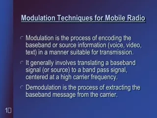
What is digital? Digital normally means binary Digital can mean: Digital techniques for analogue modes e.g. SSB AM FM (Overview in this talk) Or it can mean: Digital techniques for digital modes e.g. PSK31, GSM, DAB (a later talk)
When should one use a digital system? • This is a mixed audience with mixed views. • Amateur radio is a hobby so its up to you! • Some things people may not allow in their hobby: • Equipment built in a factory • Mobile phones • Repeaters (May as well use a mobile phone?) • Voice (only Morse) • Transistors (only Valves) • Valves not made oneself • ICs (Only transistors) • Digital (only Analogue) • PCs (only logic ICs) • Software (only non programmable Logic) • Hardware description languages (only Software)
Some reasons to use a digital system • When it is cheaper • When you want versatility • When analogue would be less practical • When analogue would be impossible! • When you want to be nearer to the leading edge • When you have seen this talk
What do we mean by doing things digitally? • We could solder together logic gates • We could use a PC • We could use a microcontroller / DSP • We could use an FPGA • Note that use of software is not necessarily required • (but it can make things a lot easier)
BITX20 bidirectional SSB transceiver Receive direction shown
The missing digital parts we need: Tuning (The SoftRock has a Fixed Xtal LO) The BFO The last mixer stage (for BFO) The audio filter The audio output
How do we do these digitally? Get our analogue signals into digital form? Generate a tuneable LO/BFO sine wave? Create In-phase and Quadrature signals? Produce the mixer stage? Filter signals? Produce the audio output?
We have seen many of these before. • Generate a tuneable LO/BFO sine wave? • We did this in our simulation spread sheet! • Create In-phase and Quadrature signals? • Our simulated Current and Voltage were I/Q! • Produce the mixer stage? • We did this in our ideal mixer talk (it’s a multiply) • Filter signals? • We already simulated an analogue RC filter
A tuneable digital oscillator In our simulation talk we simulated an RC oscillator in time steps. As we said we could have done this on a sheet of paper, one row per time step. Using a computer saves a lot of effort with a pencil but is perhaps less clear. We used a spreadsheet rather than a sheet of paper as a compromise.
Spreadsheet for a tuned circuit (See TunedA.xls for details)
In-phase and Quadrature generator based on the spreadsheet (R=0)
What are these building blocks? A latch stores a binary number. It replaces it with a new number when it gets a clock. (Our time step in the spreadsheet) As expected the adders and multipliers can add and multiply binary numbers. We will look at this another day. The circuit produces 2 sine waves (Just like the simulated Current and Voltage in our spreadsheet) These are our I and Q signals to feed to the digital mixers.
The ideal mixer Previously we looked at the electronics of mixers. An ideal mixer multiplies rather than adds waveforms. If you feed two sine waves at frequencies F and G into a multiplier you just get sine waves at frequencies F+G and F-G and no harmonics. Rather than prove this using maths we just looked at the waveforms and listened.
The inputs to the ideal mixer 2000Hz 2200Hz
The output from the ideal mixer 200Hz and 4200Hz
The components of the mixer output 200Hz 4200Hz
What else do we need? To get our analogue signals into digital form and to produce the audio output. There are many types of Analogue to Digital (A/D) and Digital to Analogue (D/A) converters. We will cover these another day. To filter signals one could simulate the equivalent analogue filter (as mentioned earlier). However there are much better ways. Such a simulation would be an approximation to what is called an IIR (infinite impulse response) filter. Our next example is an FIR filter.
The Finite Impulse Response (FIR) filter (Diagram From an Altera FPGA application note)
The basics of an FIR filter An FIR filter works in the “Time domain” It represents the filter one wants in terms of its time response ‘h()’ to an “impulse” (A very short pulse) The input waveform ‘x(n)’ (being digital) naturally can be regarded as a series of such pulses of varying height. The output waveform ‘y(n)’ is calculated by the FIR filter by adding up the response to each input “pulse” Fortunately there are standard design tools for FIR filters.
Conclusion? We did not use any software. As stated its not necessary but can make things a lot easier. In a later talk we will look at how logic gates and larger building blocks work. We will also look at CPU design. We will look at software techniques and development tools for PCs and microcontroller / DSP chips. We can build complex digital things without software if we use an FPGA. However we then need Hardware languages!
Some more real world examples follow (These next examples are from product briefs on the Broadcom public website).
MULTIFUNCTION MONOLITHIC IC: AGPS, BLUETOOTH® 2.1 + EDR, AND INTEGRATED FM TRANSCEIVER: BROADCOM BCM2075