Doodle Drive
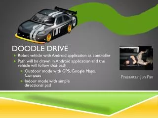
Tablet. Controlled. Doodle Drive. Vehicle. Presenter: Edward Kidarsa. Team 6. PCB LAYOUT – 7.25 x 5.45 in. Design considerations - Peripherals. GPS far away from everything Especially active circuits such as regulators Bluetooth away from power supply


Doodle Drive
E N D
Presentation Transcript
Tablet Controlled Doodle Drive Vehicle Presenter: Edward Kidarsa Team 6
Design considerations - Peripherals • GPS far away from everything • Especially active circuits such as regulators • Bluetooth away from power supply • No traces / ground plane / vias allowed under antenna • Antenna end protrude 5mm beyond any enclosure • Traces • 0.016 in used for most traces ( including power and ground for now ) • Routing • 45 degrees routings were used as much as possible • Current problem: Vias are all touching
Design Considerations - Micro • Center of PCB to be accessible to everything else • 26 pin header on each side so all 100 pins are accessible • Bypass capacitors placed next to micro before headers • External oscillator used • Located near the microcontroller after header • Routing • Pins used mainly from one side of the micro-controller, thus needed long traces and many vias were used to connect to all interfaces • Traces • Due to the small size of the pins, only 0.01 in traces were able to be used • Traces “under” micro to connect power and ground pins of micro together
Design Considerations - POwer • Power Circuit: • 2 Motors, H-Bridge, Battery Recharge Circuit, 2 Voltage Regulators • Power circuit located near edge of PCB away from transmission peripherals • Placed near each other • Power circuits may have current feedback / current spikes and may need wider traces • Unsure of trace widths for 3 different voltages • Trace under H-Bridge
Compass + Servo + ultrasonic Sensor + OPTICAL ENCODER + OSCILLATOR